154 ACS550 User’s Manual
Embedded Fieldbus
Relay Output Control
Using the fieldbus for relay output control requires:
• Drive parameter values set as defined below.
• Fieldbus controller supplied, binary coded, relay command(s) in the appropriate
location. (The location is defined by the Protocol Reference, which is protocol
dependent.)
1. More than 3 relays requires the addition of a relay extension module.
Note! Relay status feedback occurs without configuration as defined below.
Analog Output Control
Using the fieldbus for analog output control (e.g. PID setpoint) requires:
• Drive parameter values set as defined below.
• Fieldbus controller supplied analog value(s) in the appropriate location. (The
location is defined by the Protocol Reference, which is protocol dependent.)
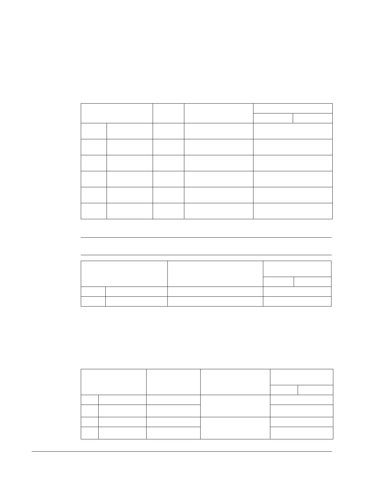
Drive Parameter Value Description
Modbus
Protocol Reference
ABB DRV DCU PROFILE
1401 RELAY OUTPUT 135 (COMM) Relay Output 1 controlled
by fieldbus.
40134 bit 0 or 00033
1402
RELAY OUTPUT 235 (COMM) Relay Output 2 controlled
by fieldbus.
40134 bit 1 or 00034
1403
RELAY OUTPUT 335 (COMM) Relay Output 3 controlled
by fieldbus.
40134 bit 2 or 00035
1410
(Note 1)
RELAY OUTPUT 435 (COMM) Relay Output 4 controlled
by fieldbus.
40134 bit 3 or 00036
1411
(Note 1)
RELAY OUTPUT 535 (COMM) Relay Output 5 controlled
by fieldbus.
40134 bit 4 or 00037
1412
(Note 1)
RELAY OUTPUT 635 (COMM) Relay Output 6 controlled
by fieldbus.
40134 bit 5 or 00038
Drive Parameter Description
Modbus
Protocol
Reference
ABB DRV DCU PROFILE
0122 RO 1-3 STATUS Relay 1…3 status. 40122
0123 RO 4-6 STATUS Relay 4…6 status. 40123
Drive Parameter Value Description
Modbus
Protocol
Reference
ABB DRV DCU PROFILE
1501 AO1 CONTENT SEL 135 (COMM VALUE 1) Analog Output 1
controlled by writing to
parameter 0135.
–
0135 COMM VALUE 1 – 40135
1507 AO2 CONTENT SEL 136 (COMM VALUE 2) Analog Output 2
controlled by writing to
parameter 0136.
–
0136 COMM VALUE 2– 40136

 Loading...


