48 ACS550 User’s Manual
Start-Up
Application Macro: PID Control
This macro provides parameter settings for closed-loop control systems such as
pressure control, flow control, etc. To enable, set the value of parameter 9902 to 6
(
PID CTRL).
Note! Parameter 2108 START INHIBIT must remain in the default setting, 0 (OFF).
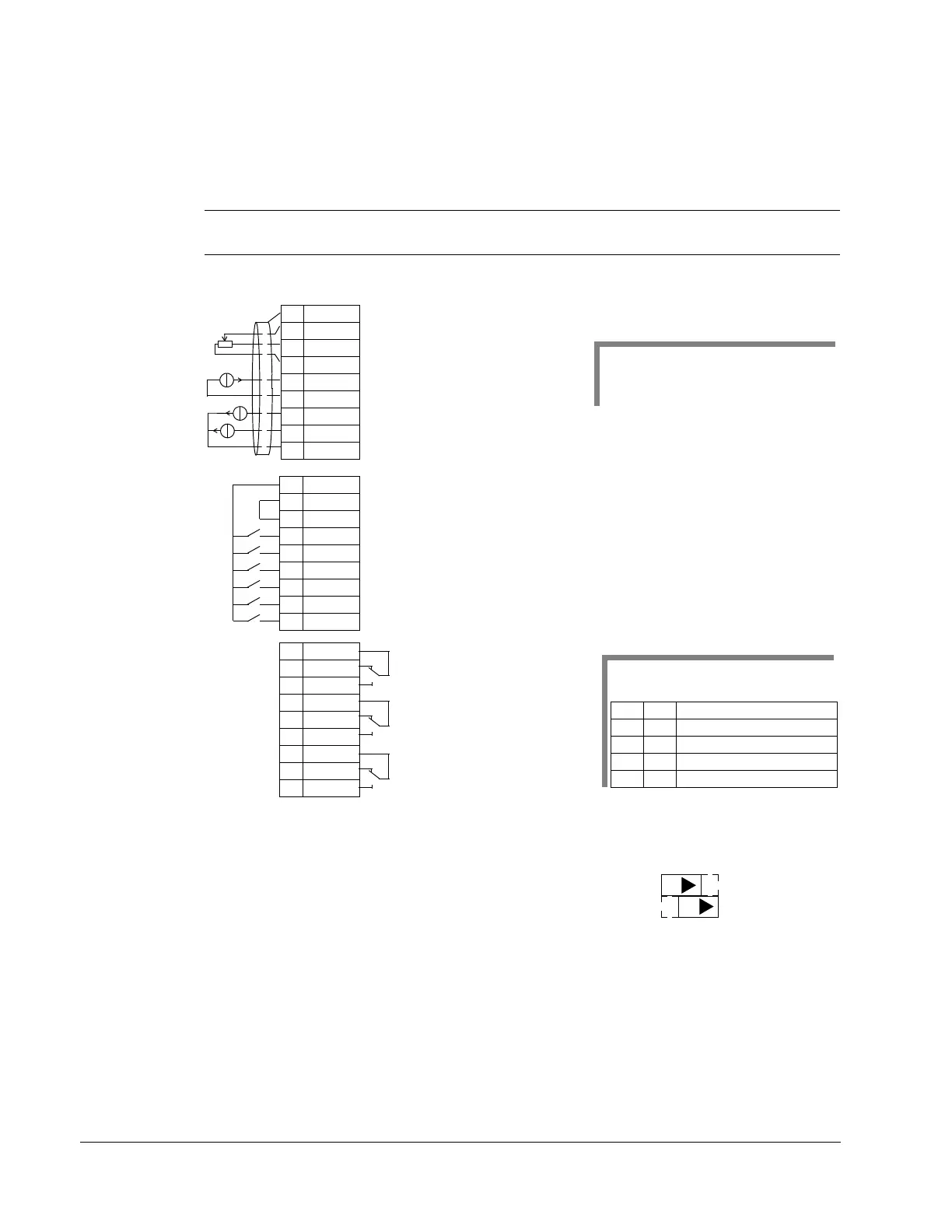
Connection example:
Input signals Output signals Jumper Setting
• Analog reference (AI1)
• Actual value (AI2)
• Start/stop – hand/PID (DI1, 6)
• EXT1/EXT2 selection (DI2)
• Constant speed selection (DI3, 4)
• Run enable (DI5)
• Analog output AO1: Speed
• Analog output AO2: Current
• Relay output 1: Ready
• Relay output 2: Running
• Relay output 3: Fault (-1)
1SCR
2AI1
3AGND
410V
5AI2
6AGND
7AO1
8AO2
9AGND
10 24V
11 GND
12 DCOM
13 DI1
14 DI2
15 DI3
16 DI4
17 DI5
18 DI6
19 RO1C
20 RO1A
21 RO1B
22 RO2C
23 RO2A
24 RO2B
25 RO3C
26 RO3A
27 RO3B
Start/Stop (Hand): Activation starts the drive
Constant speed selection 1: (Not used in PID control)
2
EXT1/EXT2 selection: Activation selects PID control
Constant speed selection 2: (Not used in PID control)
2
Start/Stop (PID): Activation starts the drive
X1
Run enable: Deactivation always stops the drive
External ref. 1 (Manual) or Ext ref. 2 (PID): 0…10 V
1
Reference voltage 10 VDC
Motor output speed: 0…20 mA
Output current: 0
…20 mA
Analog input circuit common
Analog output circuit common
Auxiliary voltage output +24 VDC
Auxiliary voltage output common
Digital input common for all
Signal cable shield (screen)
Analog input circuit common
Actual signal (PID): 0
…20 mA
Relay output 1, programmable
Default operation:
Relay output 2, programmable
Default operation:
Relay output 3, programmable
Default operation:
Ready =>19 connected to 21
Running =>22 connected to 24
Fault (-1) =>25 connected to 27
Note 2. Code:
0 = open, 1 = connected
DI3 DI4 Output
0 0 Reference through AI1
10
CONSTANT SPEED 1 (1202)
01CONSTANT SPEED 2 (1203)
11CONSTANT SPEED 3 (1204)
Note 1.
Manual: 0
…10V => speed reference
PID: 0
…10V => 0…100% PID
setpoint
(Fault => 25 connected to 26)
J1
AI1: 0
…10 V
AI2: 0(4)
…20 mA
ON
ON

 Loading...


