ACS550 User’s Manual 95
Start-Up
Group 22: Accel/Decel
This group defines ramps that control the rate of acceleration and deceleration. You
define these ramps as a pair, one for acceleration and one for deceleration. You can
define two pairs of ramps and use a digital input to select one or the other pair.
Code Description
2201 ACC/DEC 1/2 SEL
Defines control for selection of acceleration/deceleration ramps.
• Ramps are defined in pairs, one each for acceleration and deceleration.
• See below for the ramp definition parameters.
0 =
NOT SEL – Disables selection, the first ramp pair is used.
1 =
DI1 – Defines digital input DI1 as the control for ramp pair selection.
• Activating the digital input selects ramp pair 2.
• De-activating the digital input selects ramp pair 1.
2…6 =
DI2…DI6 – Defines digital input DI2…DI6 as the control for ramp pair selection.
•See
DI1 above.
7 =
COMM – Defines serial communication as the control for ramp pair selection.
-1 =
DI1(INV) – Defines an inverted digital input DI1 as the control for ramp pair selection.
• De-activating the digital input selects ramp pair 2
• Activating the digital input selects ramp pair 1.
-2…-6 =
DI2(INV)…DI6(INV) – Defines an inverted digital input DI2…DI6 as the control for ramp pair selection.
•See
DI1(INV) above.
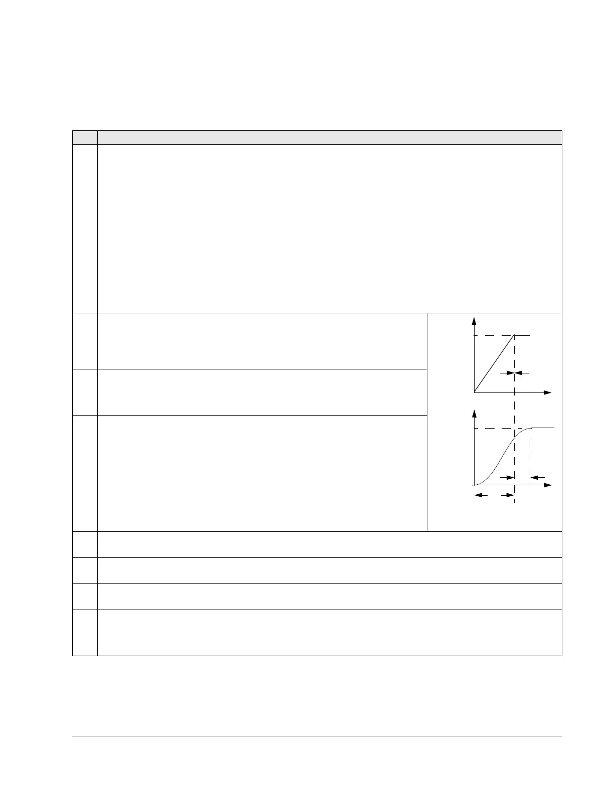
2202 ACCELER TIME 1
Sets the acceleration time for zero to maximum frequency for ramp pair 1. See A in
figure.
• Actual acceleration time also depends on 2204
RAMP SHAPE.
• See 2008
MAXIMUM FREQUENCY.
2203 DECELER TIME 1
Sets the deceleration time for maximum frequency to zero for ramp pair 1.
• Actual deceleration time also depends on 2204
RAMP SHAPE.
• See 2008
MAXIMUM FREQUENCY.
2204 RAMP SHAPE 1
Selects the shape of the acceleration/deceleration ramp for ramp pair 1. See B in
figure.
• Shape is defined as a ramp, unless additional time is specified here to reach the
maximum frequency. A longer time provides a softer transition at each end of the
slope. The shape becomes an s-curve.
• Rule of thumb: 1/5 is a suitable relation between the ramp shape time and the
acceleration ramp time.
0.0 =
LINEAR – Specifies linear acceleration/deceleration ramps for ramp pair 1.
0.1…1000.0 =
S-CURVE – Specifies s-curve acceleration/deceleration ramps for
ramp pair 1.
2205 ACCELER TIME 2
Sets the acceleration time (s) for zero to maximum frequency for ramp pair 2. See 2002
ACCELER TIME 1.
2206 DECELER TIME 2
Sets the deceleration time for maximum frequency to zero for ramp pair 2. See 2003
DECELER TIME 1.
2207 RAMP SHAPE 2
Selects the shape of the acceleration/deceleration ramp for ramp pair 2. See 2004
RAMP SHAPE 1.
2208 EM DEC TIME
Sets the deceleration time for maximum frequency to zero for an emergency.
• See parameter 2109
EM STOP SEL.
• Ramp is linear.
T
FREQ
T
MAX
FREQ
Linear
S-curve
A
A = 2202 ACCELERATION TIME
B
B (=0)
B = 2204 RAMP SHAPE
MAX

 Loading...


