220 ACS550 User’s Manual
Technical Data
Emergency Stop Devices
The overall design of the installation must include emergency stop devices and any
other safety equipment that may be needed. Pressing STOP on the drive’s control
panel does NOT:
• Generate an emergency stop of the motor.
• Separate the drive from dangerous potential.
Input Power Cables/ Wiring
Input wiring can be any of:
• A four conductor cable (three phases and ground/protective earth). Shielding is
not required.
• Four insulated conductors routed through conduit.
Size wiring according to local safety regulations, appropriate input voltage and the
drive’s load current. In any case, the conductor must be less than the maximum limit
defined by the terminal size (see "Drive’s Power Connection Terminals" on page
223).
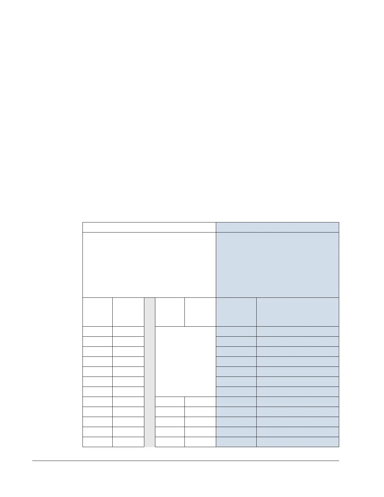
The table below lists copper and aluminum cable types for different load currents.
These recommendations apply only for the conditions listed at the top of the table.
IEC NEC
Based on:
• EN 60204-1 and IEC 60364-5-2/2001
• PVC insulation
• 30 °C (86 °F) ambient temperature
• 70 °C (158 °F) surface temperature
• Cables with concentric copper shield
• Not more than nine cables laid on cable ladder
side by side.
Based on:
• NEC Table 310-16 for copper wires
• 90 °C (194 °F) wire insulation
• 40 °C (104 °F) ambient temperature
• Not more than three current-carrying
conductors in raceway or cable, or earth
(directly buried).
• Copper cables with concentric copper shield
Max
Load
Current
(A)
Cu Cable
(mm
2
)
Max
Load
Current
(A)
Al Cable
(mm
2
)
Max Load
Current
(A)
Cu Wire Size
(AWG/kcmil)
14 3x1.5 Do not use aluminum
cable with frame sizes
R1…R4
22.8 14
20 3x2.5 27.3 12
27 3x4
36.4 10
34 3x6 50.1 8
47 3x10
68.3 6
62 3x16
86.5 4
79 3x25 100 3
98 3x35
91 3x50 118 2
119 3x50
117 3x70 137 1
153 3x70
143 3x95 155 1/0
186 3x95 165 3x120 178 2/0
215 3x120
191 3x150 205 3/0

 Loading...


