ACS550 User’s Manual 21
Installation
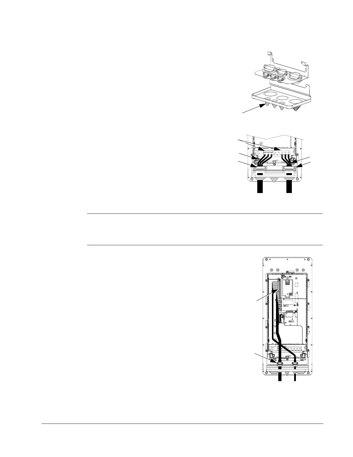
Wiring IP 54 / UL Type 12 Enclosure with Cables
1. Cut the cable seals as needed for the power,
motor, and control cables. (The cable seals are
cone-shaped, rubber seals on the bottom of the
drive.)
2. On the input power cable, strip the sheathing back
far enough to route individual wires.
3. On the motor cable, strip the sheathing back far
enough to expose the copper wire screen so that
the screen can be twisted into a pig-tail. Keep the
short pig-tail short to minimize noise radiation.
4. Route both cables through the clamps and tighten
the clamps.
5. Strip and connect the power/motor wires, and the
power ground wire to the drive terminals.
Note! For R5 frame size, the minimum power cable size is 25 mm
2
(4 AWG).
For R6 frame size, refer to "Power Terminal Considerations – R6 Frame Size" on
page 223.
6. Connect the pig-tail created from the motor cable
screen.
7. Strip control cable sheathing and twist the copper
screen into a pig-tail.
8. Route control cable(s) through clamp(s) and
tighten clamp(s).
9. Connect the ground screen pig-tail for digital and
analog I/O cables at X1-1. (Ground only at drive
end.)
10. Connect the ground screen pig-tail for RS485
cables at X1-28 or X1-32. (Ground only at drive
end.)
11. Strip and connect the individual control wires to
the drive terminals. See
"Control Terminals Table"
on page 17.
1
IP5003
4
5
2
IP5004
3
4
9…11
8
IP5005

 Loading...


