ACS550 User’s Manual 43
Start-Up
Application Macro: ABB Standard (Default)
This macro provides a general purpose, 2-wire I/O configuration, with three (3)
constant speeds. This is the default macro. Parameter values are the default values
defined in the "Complete Parameter List for ACS550" on page 53.
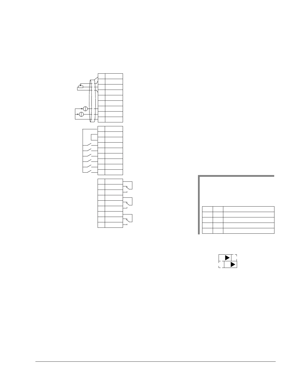
Connection example:
Input signals Output signals Jumper Setting
• Analog reference (AI1)
• Start, stop and direction (DI1,2)
• Constant speed selection (DI3,4)
• Ramp pair (1 of 2) selection (DI5)
• Analog output AO1: Frequency
• Analog output AO2: Current
• Relay output 1: Ready
• Relay output 2: Running
• Relay output 3: Fault (-1)
1SCR
2AI1
3AGND
4 10V
5AI2
6AGND
7AO1
8AO2
9AGND
10 24V
11 GND
12 DCOM
13 DI1
14 DI2
15 DI3
16 DI4
17 DI5
18 DI6
19 RO1C
20 RO1A
21 RO1B
22 RO2C
23 RO2A
24 RO2B
25 RO3C
26 RO3A
27 RO3B
External frequency reference 1: 0…10 V
Reference voltage 10 VDC
Output frequency: 0
…20 mA
Start/Stop: Activate to start
Fwd/Rev: Activate to reverse rotation direction
Constant speed selection
2
Constant speed selection
2
Ramp pair selection: Activate to select 2nd acc/dec ramp pair
Relay output 1, programmable
Default operation:
Relay output 2, programmable
Default operation:
Relay output 3, programmable
Default operation:
Note 1. The external reference is
used as a speed reference, if a vector
mode is selected,
Note 2. Code:
0 = open, 1 = connected
DI3 DI4 Output
0 0 Reference through AI1
10
CONSTANT SPEED 1 (1202)
01
CONSTANT SPEED 2 (1203)
11CONSTANT SPEED 3 (1204)
X1
Output current: 0
…20 mA
Not used
Ready =>19 connected to 21
Running =>22 connected to 24
Fault (-1) =>25 connected to 27
Analog input circuit common
Not used
Analog output circuit common
Auxiliary voltage output +24 VDC
Auxiliary voltage output common
Digital input common for all
Signal cable shield (screen)
Analog input circuit common
(Fault => 25 connected to 26)
J1
AI1: 0
…10 V
AI2: 0(4)
…20 mA
ON
ON

 Loading...


