Modbus/TCP – Start-up 69
The minimum and maximum 16-bit integer values that can be
given through the fieldbus are -32768 and 32767 respectively.
The table below gives the recommended drive parameter settings.
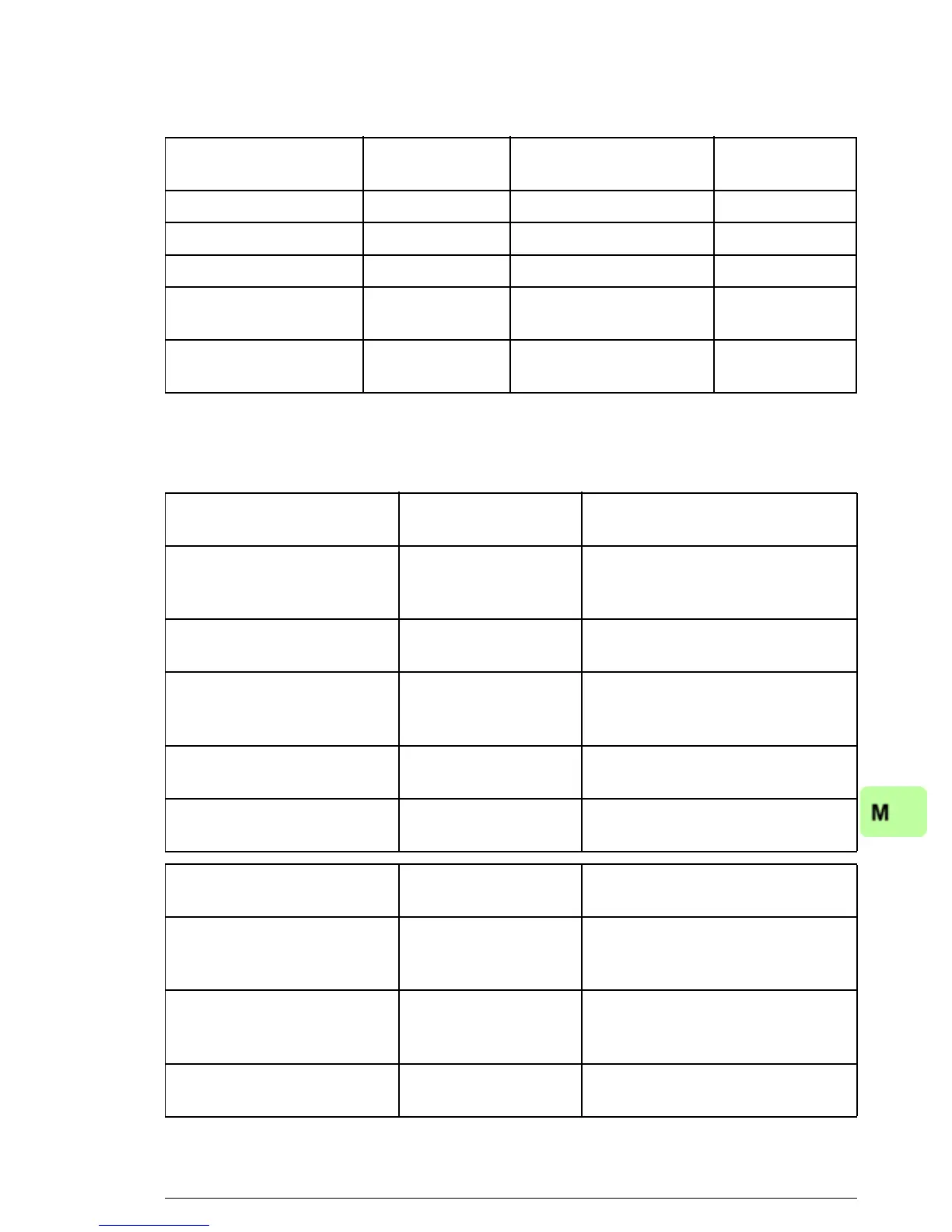
Output data Modbus
register
Input data Modbus
register
Control word (4)00001 Status word (4)00051
Speed reference (4)00002 Speed actual value (4)00052
Torque reference (4)00003 Torque actual value (4)00053
Constant speed
1)
(4)00004
(4)00005
Power
1)
(4)00054
(4)00055
Speed reference for
jogging function 1
1)
(4)00006
(4)00007
DC bus voltage
1)
(4)00056
(4)00057
1)
Example
Drive parameter Setting for ACSM1
drives
Description
50.01 FBA ENABLE Enable Enables communication
between the drive and the
fieldbus adapter module.
50.02 COMM LOSS FUNC Fault
2)
Enables fieldbus communication
fault monitoring.
50.03 COMM LOSS T OUT 3.0 s
2)
Defines the fieldbus
communication break
supervision time.
50.04 FBA REF1
MODESEL
Speed Selects the fieldbus reference 1
scaling.
50.05 FBA REF2
MODESEL
Torque Selects the fieldbus reference 2
scaling.
51.01 FBA TYPE ETHERNET
1)
Displays the type of the fieldbus
adapter module.
51.02 FBA PAR2
(PROTOCOL/PROFILE)
1 (= MB/TCP ABB E) Selects the Modbus/TCP
protocol and the ABB Drives -
Enhanced profile.
51.03 FBA PAR3
(COMMRATE)
0 (= Auto)
2)
Ethernet communication rate is
negotiated automatically by the
device.
51.04 FBA PAR4
(IP CONFIGURATION)
0 (= Static IP)
2)
Configuration will be obtained
from parameters 05…13.

 Loading...