EasyManua.ls Logo

ABB PVI-6.0-TL-OUTD User Manual

ABB PVI-6.0-TL-OUTD
107 pages
To Next Page IconTo Next Page
To Previous Page IconTo Previous Page
Page #57 background imageLoading...
Page #57 background image
- 57 -
000440AG
5 - Installation
Connections to the communication and control board
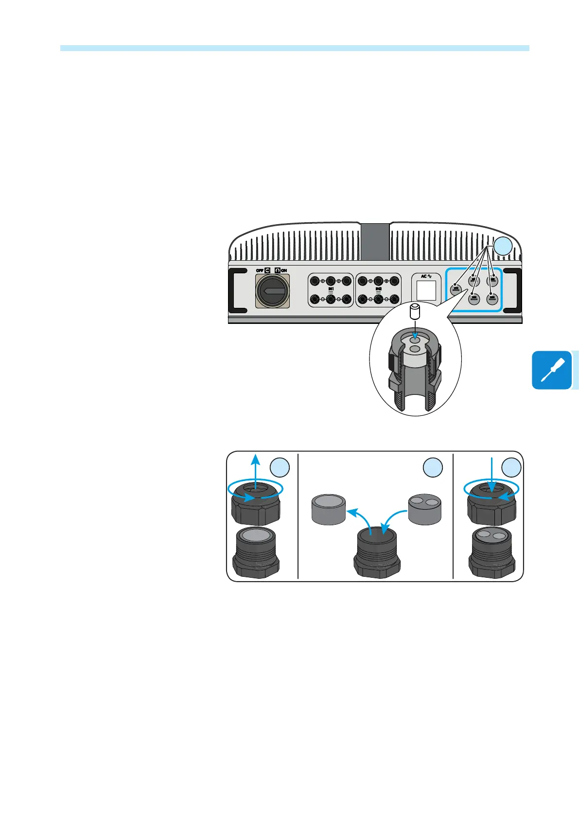
Each cable which must be connected to the communication and control
board must pass through one of the ve service cable glands.
• An M20 that takes cables from 7 mm to 13 mm in diameter. Gaskets
with two holes are supplied as standard to insert into the cable gland,
which enables two separate cables of a maximum cross-section of 5 mm
to be accommodated.
A B C

Table of Contents

Other manuals for ABB PVI-6.0-TL-OUTD

Question and Answer IconNeed help?

Do you have a question about the ABB PVI-6.0-TL-OUTD and is the answer not in the manual?

ABB PVI-6.0-TL-OUTD Specifications

General IconGeneral
BrandABB
ModelPVI-6.0-TL-OUTD
CategoryInverter
LanguageEnglish

Related product manuals