- 68 -
000034EG
7 - Operation
LED behaviour
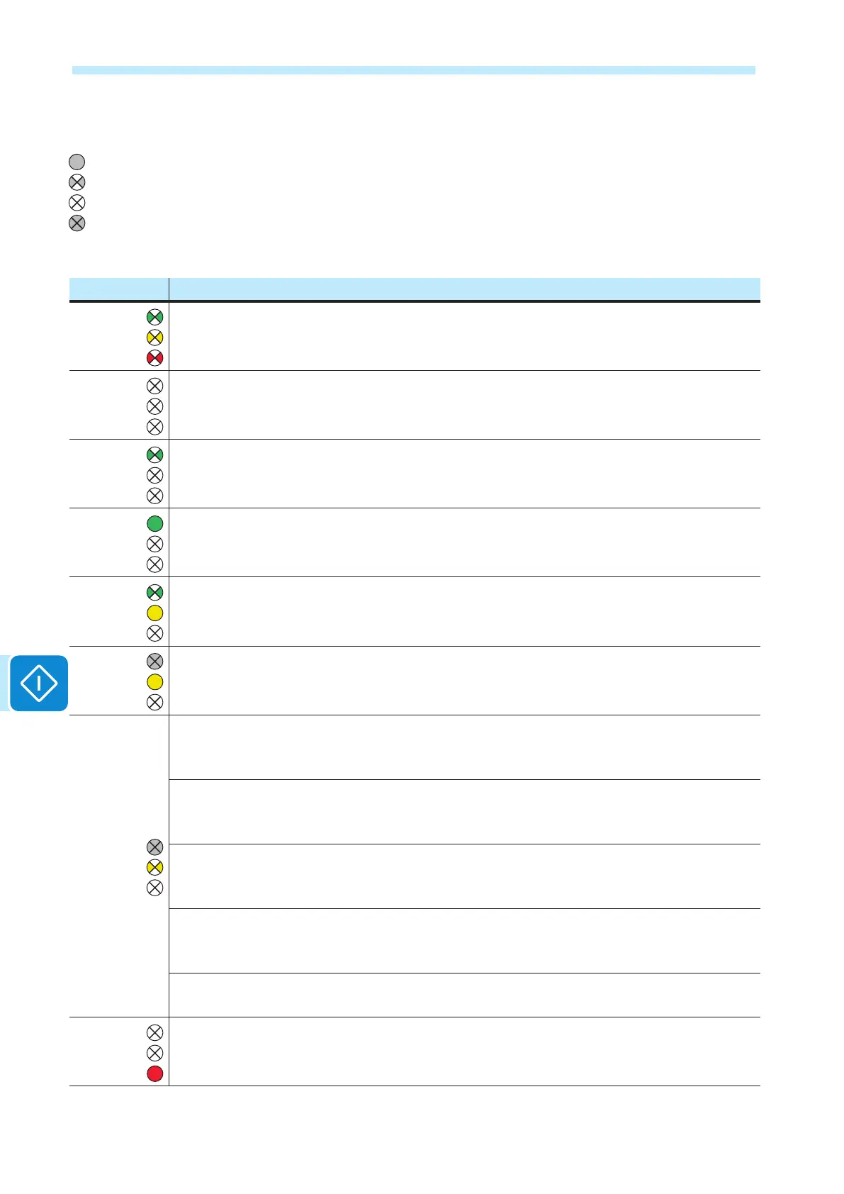
The following table shows all the possible activation combinations of LEDs
on the LED panel according to the operating status of the inverter.
LED status Operating state
green:
yellow:
red:
Firmware programming
The inverter rmware is being programmed
green:
yellow:
red:
Night mode (inverter automatically switches off)
The inverter is in night time switch-off mode (input voltage less than 70% of the set start-up
voltage).
green:
yellow:
red:
Inverter initialisation
This is a transitional state during verication of the operating conditions. During this stage the
inverter checks that the conditions for connecting to the grid are met.
green:
yellow:
red:
The inverter is connected and is feeding power into the grid
Normal operation During this stage, the inverter automatically tracks and analyses the photo-
voltaic generator's maximum power point (MPP).
green:
yellow:
red:
Disconnection from the grid
Indicates no grid voltage. This condition does not allow the inverter to connect to the grid (the
inverter display shows the message "Missing Grid").
green:
yellow:
red:
Indication of Warning (W message codes) or Error (E message codes) states
Indicates that the inverter control system has detected a warning (W) or error (E). The display
shows a message indicating the type of problem found (see Alarm messages).
green:
yellow:
red:
• Ventilation anomaly
Indicates an anomaly in the operation of the internal ventilation system that could limit output
power at high ambient temperatures.
• Failed association of internal inverter components (after replacement)
Indicates that the installed wiring box (only in the event of a replacement) was already associ-
ated with another inverter and cannot be associated with the new inverter
• Overvoltage surge arresters triggered (where tted)
Indicates that any class II overvoltage surge arresters installed on the AC or DC side have
been triggered
• String protection fuses triggered (where tted)
Indicates that one or more input string protection fuses that may be installed have been trig-
gered
• Autotest (for Italian grid standards only)
The inverter is performing a self-test
green:
yellow:
red:
Anomaly in the insulation system of the photovoltaic generator
Indicates that a leakage to ground from the FV generator has been detected, causing the
inverter to disconnect from the grid.
= LED On
= LED ashing
= LED Off
= Any one of the conditions
described above

 Loading...


