- 59 -
000440AG
5 - Installation
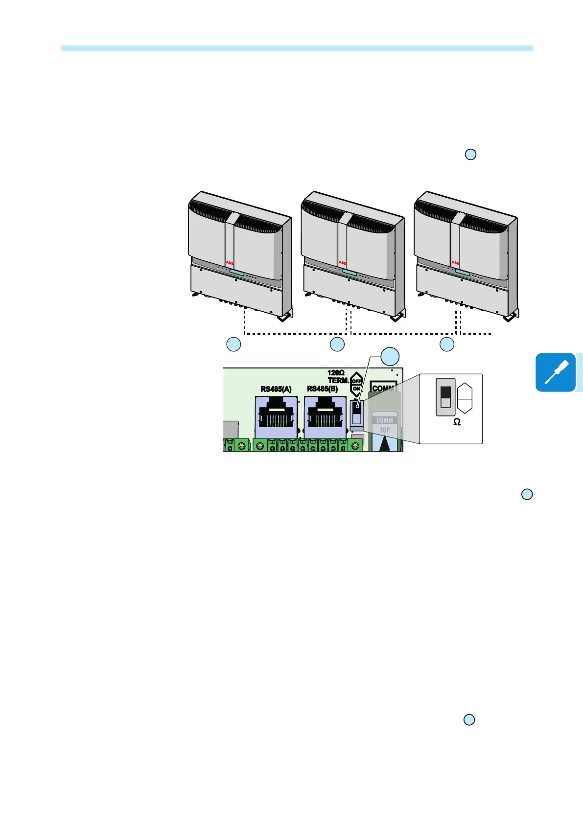
Procedure for connection to a monitoring system
Connect all the units of the RS485 chain in accordance with the “daisy-
chain” arrangement (“in-out”) observing the correspondence between
signals, and activate the termination resistance of the communication
line in the last element of the chain by switching switch
20
(to ON posi-
tion).
120
TERM.
ON
OFF
20
Monitor
= OFF
20
= OFF
20
= ON
20
TRIO
TRIO
TRIO
If a single inverter is connected to the monitoring system, activate the
termination resistance of the communication line by switching switch
20
(to ON position).
Set a different RS485 address on each inverter of the chain. No inverter
should have “Auto” as its address. An address can be chosen freely
from out of 2 to 63.
The address on the inverter is set through the display and the push-
button panel (see relevant chapter).
We recommend not exceeding a length of 1000m for the communication line.
No more than 62 inverters can be connected to the same RS485 line.
When using an RS-485 connection, if one or more inverters are added
later to the system, you must remember to return to OFF position the
switch of the termination resistance used of the inverter that was previ-
ously the last one of the system.
Each inverter is dispatched with two (2) as the predened RS485 ad-
dress and with switch for setting termination resistance
20
to OFF posi-
tion.

 Loading...


