TPU2000/2000R Modbus/Modbus Plus/ Modbus TCP/IP Automation Guide
114
• Trip Initiation
• Enable/Disable of Protective Functions
• Clearing of Event Counters
• Enable/Disable of Supervisory Functions
• Reset of Targets
• Clear of Seal In’s
Function Code 16 Preset 4X Registers (Write Only)
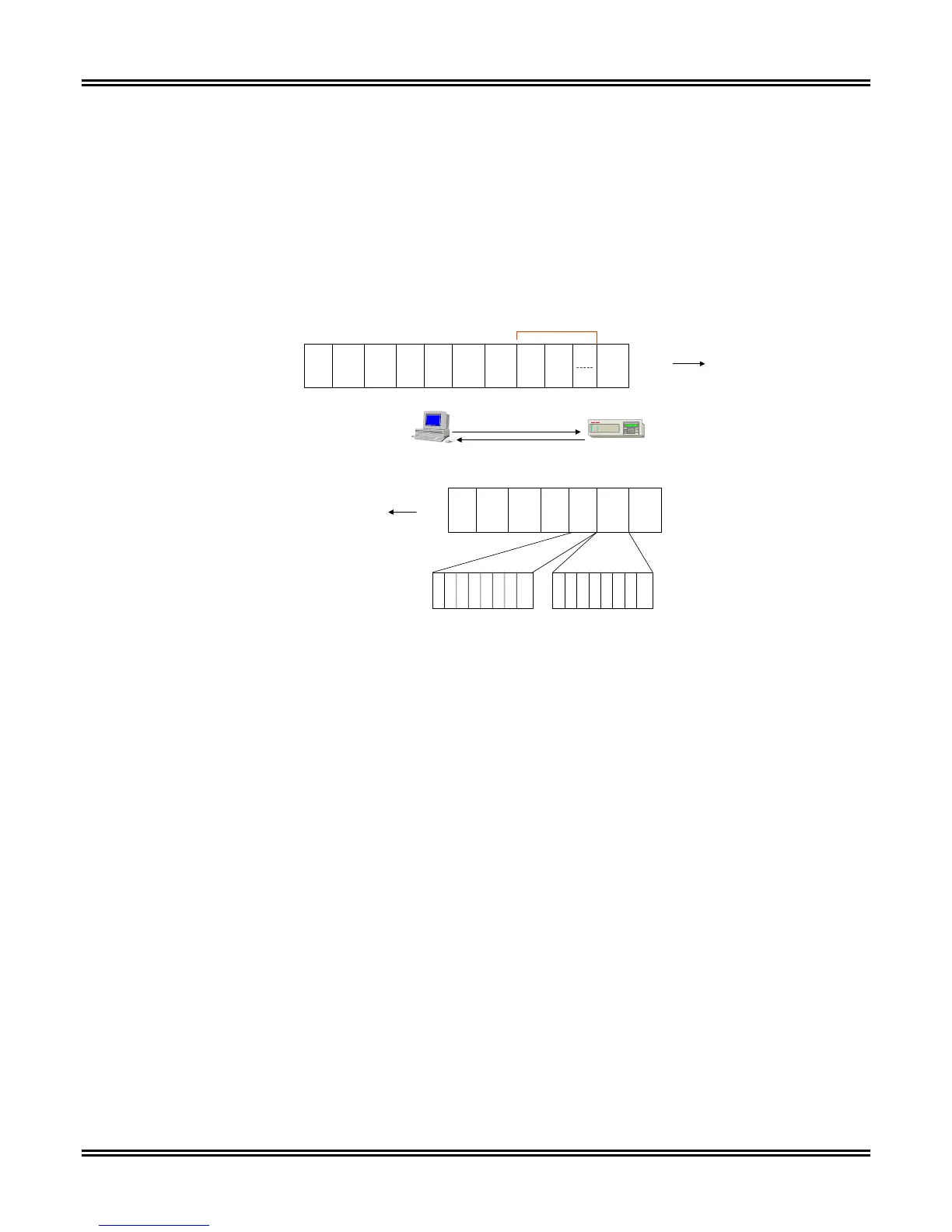
Figure 5-37 illustrates the Modbus command structure writing multiple registers.
Function 16 Preset Multiple Registers
Modbus Host
Modbus Slave Addr =1
Read from
4X Mapping
Slave
Addr.
Funct.
Code
10
Start
Addr
HI
Start
Addr
LO
Regs
Writ
HI
Regs
Writ
LO
# *
Bytes
Writ.
EOMSOM
Slave
Addr.
Funct.
Code
10
Start
Addr
HI
Start
Addr
LO
Regs
Sent
HI
Regs
Sent
LO
Error
Check
EOM
SOM
Byte 1 …2……..3…….4…….5……6……..7…. ..8………9…………X...
MSB LSB
151413121110 9 8 76543210
MSB
LSB
Register Hi Byte
Data
HI
Data
LO
Error
Check
Command
Allows 125 Regs.
Max.
E
C
SOM = Start of Message
EOM = End of Message
Figure 5-37. Modbus Write Command 16 (10 Hex) Allowing Writes to the TPU2000/2000R
The write multiple register command is convenient for writing the following control blocks:
Control Block 1 allows for:
• Initiation of Relay Trip
• Initiation of Input Functions
Control Block 2 allows for:
• Forcing of Physical Input Logical Statuses
Control Block 3 allows for:
• Force of Physical Output Points
Control Block 4 allows for:
• Force Logical Input Bits 1 to 32
Control Block 5 allows for:
• Setting and Resetting of Protective Functions and Resetting of Alarms
Control Block 6 allows for:
• Forcing of Physical Output Points for a limited duration of time
Whenever a write occurs to the TPU2000/2000R:
• The TPU2000/2000R receives the command:
• Command Interpreted in 1 quarter cycle.
• Relay Protection Occurs.
• Command acts on the device.
 Loading...