TPU2000/2000R Modbus/Modbus Plus/ Modbus TCP/IP Automation Guide
122
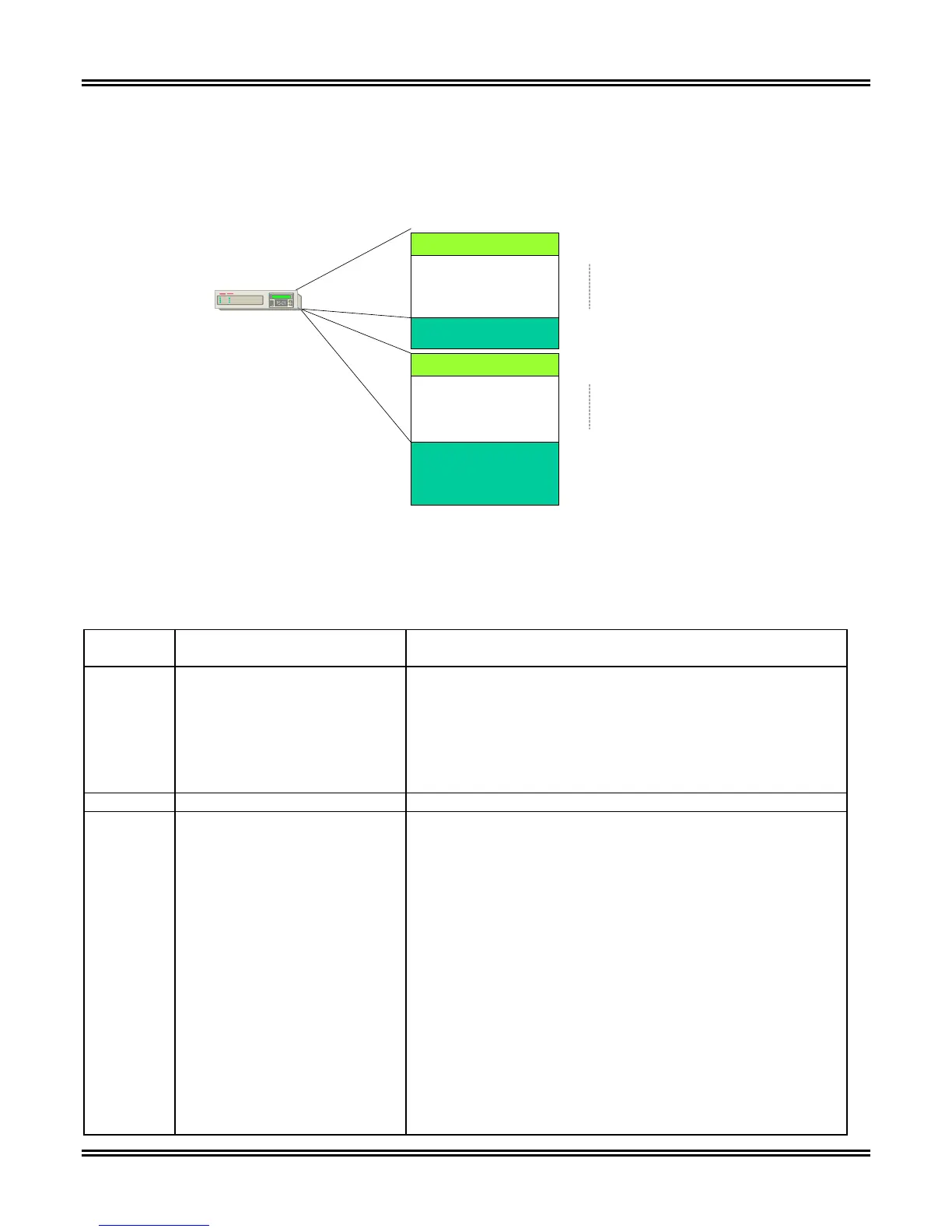
Thirty two through faults are stored within the TPU2000/2000R. A through-fault is stored on any overcurrent trip
output or whenever the Disturbance-2 pickup setting is exceeded. Within the TPU2000 and TPU2000R the two
Winding Through Fault buffer described in Table 5-35 allows the user to obtain the fault information. In a
TPU2000R Three Winding Unit, additional fault information may be retrieved describing the fault conditions for the
third winding.
Through Fault Record Layout (TPU2000/TPU2000R)
Data Control Register
Through Fault Data
TPU 2000 and
TPU 2000R
41793
41794
41830
Through Fault
Data Control Register
Through Fault
Data TPU 2000R
Only (3 Winding)
42433
42434
42466
32 Faults in Stack Max..
32 Faults in Stack Max.
Fault Stack
Fault Stack
Third Winding
Through Fault
Data
E
C
Figure 5-41. Event Record Access Illustration of Function 23 is Issued to a TPU2000/2000R
Device
Table 5-35. 2 Winding Through Fault Register Definition for the TPU2000/TPU2000R
Register
Address
Item Description (Multiplier if any)
41793 2 Winding Through Fault
Control Register
1 = First Record
2 = Next Record
3 = Oldest Unreported Record
Fault Record Control Register
Unsigned 16 Bit
1 = Fill 41794 through 41830 with First Record in Data Buffer.
2 = Fill 41794 through 41830 with next Record Data pointed
to in buffer.
3 = Fill 41794 through 41830 with the last (oldest unreported)
record of data.
41794 Parameter Flag Unsigned Integer 16 Bit
41795 Fault Type Element Unsigned 16 Bit
00 = 87T – % Differential Alarm
01 = 87H – High Set Inst. Differential Alarm
02 = 51P-1 – Winding 1 Phase Time Overcurrent
03 = 51P-2 – Winding 2 Phase Time Overcurrent
04 = 50P-1 – 1
st
Winding 1 Phase Inst. Overcurrent
05 = 50N-1 – 1
st
Winding 1 Neutral Inst. Overcurrent
06 = 150P-1 – 2
nd
Winding 1 Phase Inst. Overcurrent
07 = 150N-1 – 2
nd
Winding 1 Neutral Inst. Overcurrent
08 = 46-1 – Neg. Sequence 1 Inst. Time Overcurrent
09 = 51P-2 – Winding 2 Phase Time Overcurrent
10 = 51G-2 – Winding 2 Ground Time Overcurrent
11 = 50P-2 – 1
st
Winding 2 Phase Inst. Overcurrent
12 = 50G-2 – 1
st
Winding 2 Ground Inst. Overcurrent
13 = 150P-2– 2
nd
Winding 2 Phase Inst. Overcurrent
14 = 150G-2– 2
nd
Winding 2 Ground Inst. Overcurrent
15 = 46-2 – Neg. Sequence 2 Inst. Time Overcurrent
16 = ECI-1 – Event Capture Initiate 1
 Loading...