TPU2000/2000R Modbus/Modbus Plus/ Modbus TCP/IP Automation Guide
44
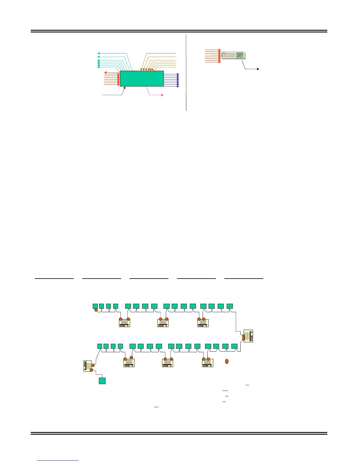
Modbus Plus Node
(Maximum Implementation)
8 Data Master Paths
8 Data Slave Paths
Global Data Read Global Data Write
8 Program Master Paths
8 Program Slave Paths
E
C
8 Data Slave Paths
Global Data Out
Figure 5-12. Modbus Plus Path Designation
The TPU2000R implementation of Modbus Plus shows the data path implementation. The TPU2000R Modbus
Plus implementation allows:
The TPU2000R to receive information requests from a device acting as a host along one of its 8 data
slave paths.
The TPU2000R to place up to 32 registers of data on the Global Out Data Path. The data sent on the
Global Out Path is configurable through ECP or WinECP. The Configuration Method is described in
Section 4.
The TPU2000R implements Modbus Plus as a HOST device. The Modbus Plus address assignment required
depends upon the understanding of the path assignment discussion. Figure 5-13 illustrates the addressing
required when a device (such as a programmable logic controller or a host device with a Modbus Plus SA 85
card) must access a TPU2000R via Modbus Plus. An application note is included in Appendix C describing the
process for Programmable Logic Controller attachment with a TPU2000R. This application note can easily be
applied in connecting a TPU2000R to a Programmable Logic Controller Network.
As per Figure 5-13, if a host device X is to request data from an ABB TPU2000R, the node address (configured
via the front panel interface, ECP, or WinECP) is the first address node entry in the data path for the address
Routing Path 1. In the case with the nodes sharing the same network, the Routing Path 2 entry is the slave path
address communicated with. The Route address for the slave path is 1 through 8.
Routing Addr 1 Routing Addr 2 Routing Addr 3 Routing Addr 4 Routing Addr 5
5 1 0 0 0
64 Nodes Maximum with 6000’ of cable
1500 ‘ Repeater 1500’ Repeater 1500 ‘ Repeater 1500 ‘
1500 ‘ Repeater 1500’ Repeater 1500 ‘ Repeater 1500 ‘
Bridge
Bridge
1
64
1
64
12
3 4 5 6 27 28 29 21 22 23 24 25 26 42 52
2
12
22 32
Segment 1
Segment 2 Segment 3 Segment 4
= Line Termination
31303 34 52532928357 8 9
NETWORK 1
NETWORK 2
X
Q
Z
W
From X (Host) to Q (DPU 2000R) = Same network = 28.A.0.0.0
From X (Host) to Z = Thru Networks = 1.22.A.
0.0
From X(Host) to N = Thru Networks = 1.1.33.A
.0
From W (Host) to Z = Thru Networks = 1.12.A
.0.0
(NOTE A
= Slave Path Number from 1 to 8)
33
N
Figure 5-13. Modbus Plus Addressing Example
 Loading...