TPU2000/2000R Modbus/Modbus Plus/ Modbus TCP/IP Automation Guide
192
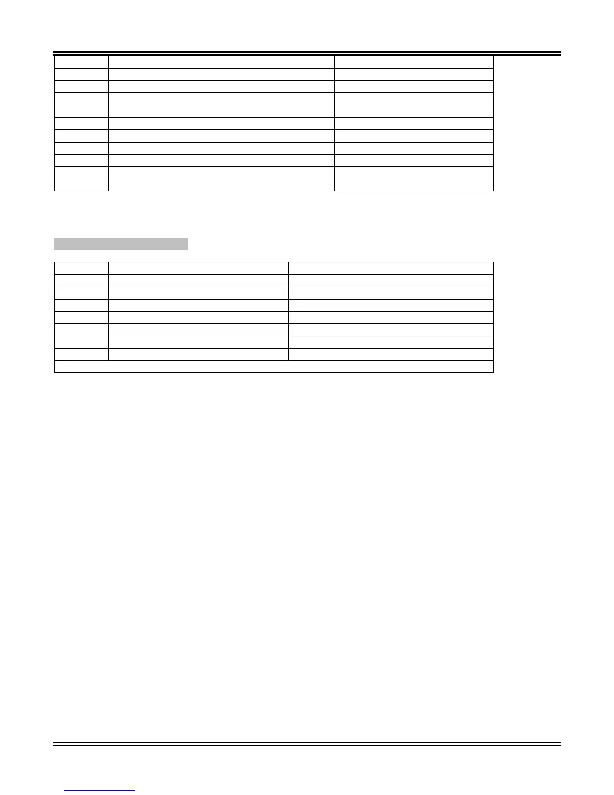
Address Item Description
60662 OUTPUT 6 Characters 2 Digit ASCII Characters
60663 OUTPUT 6 Leftmost 2 Characters 2 Digit ASCII Characters
60664 OUTPUT 7 Rightmost 2 Characters 2 Digit ASCII Characters
60665 OUTPUT 7 Characters 2 Digit ASCII Characters
60666 OUTPUT 7 Characters 2 Digit ASCII Characters
60667 OUTPUT 7 Leftmost 2 Characters 2 Digit ASCII Characters
60668 Reserved
60669 Reserved
60670 Reserved
60671 Reserved
Each of the Programmable Output’s may be delayed to operate on a time setting. The timer configuration
settings are configured by the settings transferred to Registers 60768 through 60775.
Table 5-65. To Be Named
Address Item Description
60768 OUT 5 delay in 0.01 sec inc Unsigned Integer 16 Bits (See Note 1)
60769 OUT 7 delay in 0.01 sec inc Unsigned Integer 16 Bits (See Note 1)
60770 OUT 4 delay in 0.01 sec inc Unsigned Integer 16 Bits (See Note 1)
60771 OUT 6 delay in 0.01 sec inc Unsigned Integer 16 Bits (See Note 1)
60772 OUT 3 delay in 0.01 sec inc Unsigned Integer 16 Bits (See Note 1)
60773 OUT 2 delay in 0.01 sec inc Unsigned Integer 16 Bits (See Note 1)
60774 OUT 1 delay in 0.01 sec inc Unsigned Integer 16 Bits (See Note 1)
Note 1: Range is as Such 0.00 <= Range <=60 * 100
Settings
There are three setting groups (PRIMARY, ALT 1 and ALT 2) possible in the TPU2000 and TPU2000R.
However, the number of defined registers to read or transmit for the configuration process may vary depending
upon the TPU model number one would purchase. If one has a 3 Winding TPU2000R, additional blocks of
registers must be read for the following 3 Winding Configuration Data:
• Primary Settings
• Alternate 1 Settings
• Alternate 2 Settings
• Configuration Settings
• Counter Settings
• Alarm Settings
The selections are determined by the control bits set for group selection (Reference Section 5). The relay
settings are configured via a selected CURVE SELECTION TYPE. These are based on different functions such
as:
CURVE SELECTIONS
MODE SELECTIONS
The curve selection types are based upon whether the relay is an ANSI or IEC type. The following is the
description of the codes to select the curve and recloser curves.
High byte consists of bits 15 through 8.
Low byte consists of bits 7 through 0.
(Note Bit 0 is the right most bit whereas bit 15 is the left most bit)
 Loading...