TPU2000/2000R Modbus/Modbus Plus Automation Guide
149
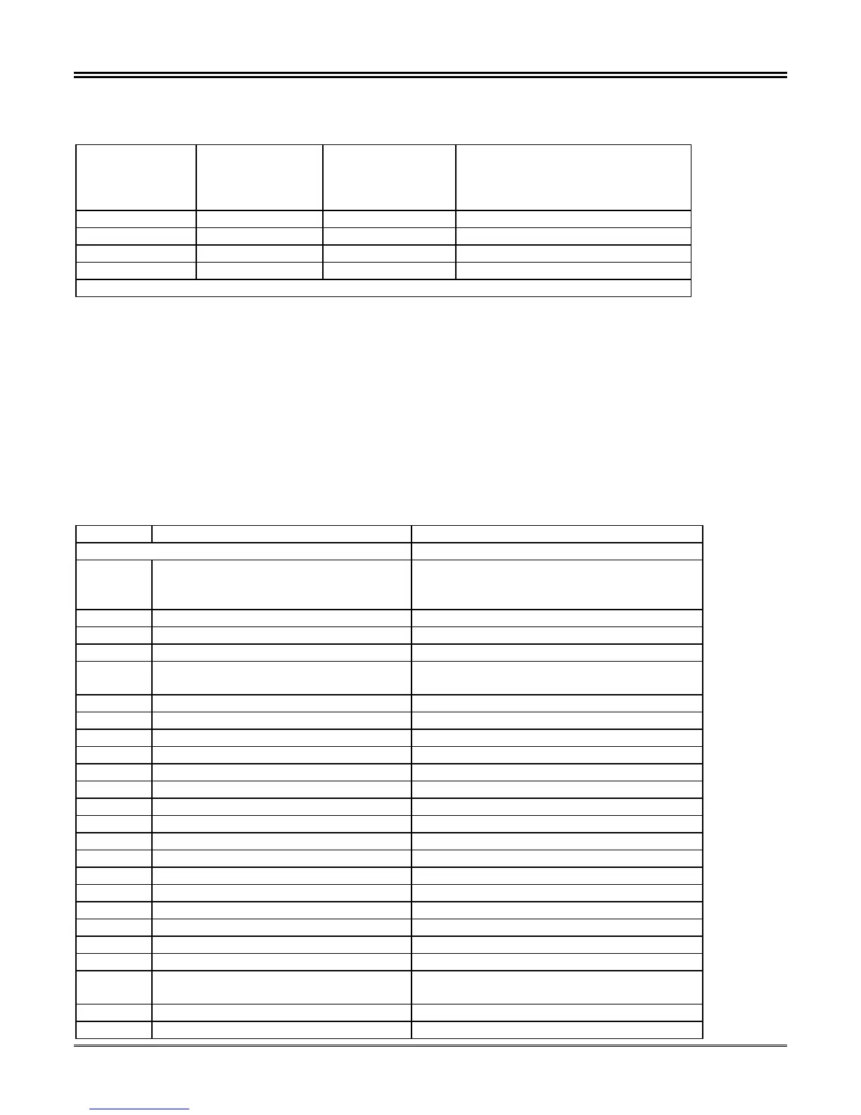
A Truth Table for the aforementioned bits follows as illustrated in Table 5-48:
Table 5-48. State Truth Chart for Physical Input Forcing Function
Bit Value
Change Mask
Register 41434
and 41435
Bit Value
Normal/Forced
Mask Register
41436 and 41437
Bit Value
Forced State
Register 41438
and 41439
Description
0 X X Normal - State Unforced
1 0 X Normal - State Unforced
1 1 0 Logical Input Forced – State = OFF
1 1 1 Logical Input Forced – State = ON
Note: X = Don’t Care State
. There are three modes which a Physical Output may be placed:
• UNFORCED – The TPU2000/TPU2000R Logical Input is not forced to any state.
• FORCED ON – The TPU2000/TPU2000R Logical Input is energized and associated mapped function
is enabled. The Logical Input status is reported as a 1. If the point status is viewed via ECP or
WinECP, the Logical point will show a forced status with a logical state of 1.
• FORCED OFF – The TPU2000/TPU2000R Logical Input is de-energized. The Logical Input status is
reported as a 0. If the point status is viewed via ECP or WinECP, the point will show a forced status
with a logical state of 0.
Table 5-49. TPU2000 and TPU2000R Bit Control Function Definitions
Register Item Description
GROUP IV
41430 Execute Register
0 = No Action
1 = Execute
Unsigned (16 Bits)
41431 Password ASCII – 2 Characters Leftmost Digits
41432 Password ASCII – 2 Characters Rightmost Digits
41433 Spare
41434 Force Logical Input Change Mask
FLI 17 to FLI 32
Unsigned (16 Bits)
1 = Control Bit State 0 = No Control
Bit 0 FLI 17(lsb) 1 = Control Bit State 0 = No Control
Bit 1 FLI 18 1 = Control Bit State 0 = No Control
Bit 2 FLI 19 1 = Control Bit State 0 = No Control
Bit 3 FLI 20 1 = Control Bit State 0 = No Control
Bit 4 FLI 21 1 = Control Bit State 0 = No Control
Bit 5 FLI 22 1 = Control Bit State 0 = No Control
Bit 6 FLI 23 1 = Control Bit State 0 = No Control
Bit 7 FLI 24 1 = Control Bit State 0 = No Control
Bit 8 FLI 25 1 = Control Bit State 0 = No Control
Bit 9 FLI 26 1 = Control Bit State 0 = No Control
Bit 10 FLI 27 1 = Control Bit State 0 = No Control
Bit 11 FLI 28 1 = Control Bit State 0 = No Control
Bit 12 FLI 29 1 = Control Bit State 0 = No Control
Bit 13 FLI 30 1 = Control Bit State 0 = No Control
Bit 14 FLI 31 1 = Control Bit State 0 = No Control
Bit 15 FLI 32 (msb) 1 = Control Bit State 0 = No Control
41435 Force Logical Input Change Mask
FLI 01 to FLI 16
Unsigned (16 Bits)
1 = Control Bit State 0 = No Control
Bit 0 FLI 01(lsb) 1 = Control Bit State 0 = No Control
Bit 1 FLI 02 1 = Control Bit State 0 = No Control
 Loading...