TPU2000/2000R Modbus/Modbus Plus/ Modbus TCP/IP Automation Guide
116
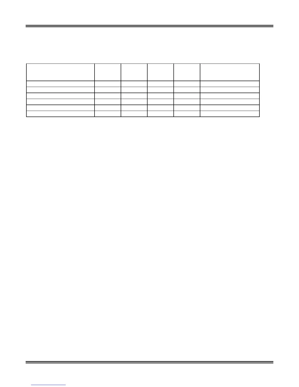
Table 5-32. Fault Record Data Assignment
Description Control
Register
Address
Buffer
Start
Address
Buffer
End
Address
Buffer
Register
Size
Notes
Differential Fault Records 41665 41666 41745 80 2 Winding Records Only
Through Fault Records 41793 41794 41830 37 2 Winding Records Only
Harmonic Restraint Records 41921 41922 42009 88 2 Winding Records Only
Differential Fault Records 42305 42306 42352 47 3 Winding Records Only
Through Fault Records 42433 42434 42466 33 3 Winding Records Only
Differential Fault Records 42561 42562 42601 40 3 Winding Records Only
If the number of faults exceed 32, then the buffer overwrites the oldest record contained within its internal stack.
Access and control can be accomplished over Modbus in one of two methods.
If no data accumulated within the fault record, values of 0 shall be returned in the buffer. A new fault record entry
is indicated via Bit 6 of Register 40129 being set to a 1. Reference Table 5-9 of this document for a more detailed
explanation of the registers bit map.
The Fault Record number can be a number from 1 to 999. ONLY THE PREVIOUS 32 RECORDS ARE KEPT IN
THE FAULT RECORD BUFFER. Fault Records are sequentially numbered from 1 to 999. If the fault number is
presently at 999, and an additional fault is recorded, the fault number shall rollover to 1. The Record number and
fault buffer cannot be cleared and reset through a keypad or unit reset procedure or a reset via the network as
explained in Section 3 as a note.
METHOD 1:
The host writes a Modbus 23 Command (Modbus 4X Register Read/Write) in which a control code (1, 2,
or 3) is written to The Fault Control Register Address as defined in Table 1 and the buffer is filled with
fault data from the Fault Buffer Start until the Buffer End address. A command of 1 = Points to the First
Record in the Fault Table. A command of 2 Points to the next fault in the fault table. A command of 3
points to the last unreported fault in the fault table. Figure 5-39 graphically illustrates the write/read
process for access of fault or operation records.
METHOD 2:
The host writes a Modbus Command 16 (Modbus 4X Register Write Command) in which a control code
(1, 2, or 3) is written to the Fault Control Register Address as defined in Table 5-32 and the buffer is filled
with fault data in the addresses defined for the Fault Buffer (reference Table 5-32). Within 10 seconds
after the 16 command is issued, the host issues a Modbus 03 command (Modbus 4X Register Read
command) in which the fault data is retrieved from the Fault Buffer as defined for the retrieved fault.
 Loading...