TPU2000/2000R Modbus/Modbus Plus/ Modbus TCP/IP Automation Guide
152
Group V Control Features Explained
Group V control functions allow the resetting of specific alarms and/or the setting AND resetting of ULO states.
Group 1 allows certain reset of alarms, targets, as well as other features. Group V allows reset of individual
TPU2000 and TPU2000R alarm status bits. Within Tables 5-50 and 5-51, the mapping is described for controlled
reset of the specific elements. Table 5-52 contains a mapping of which bits only are controlled by reset
commands.
Group IV functions operate as follows:
Register 41444 = Set/Reset Change Mask - Features 1
Register 41445 = Set/Reset Change Mask - Features 2
Register 41446 = Set/Reset Change Mask - Features 3
Register 41447 = Set/Reset Change Mask - Features 4
Register 41448 = Set/Reset State Change - Features 1
Register 41449 = Set/Reset State Change - Features 2
Register 41450 = Set/Reset State Change - Features 3
Register 41451 = Set/Reset State Change - Features 4
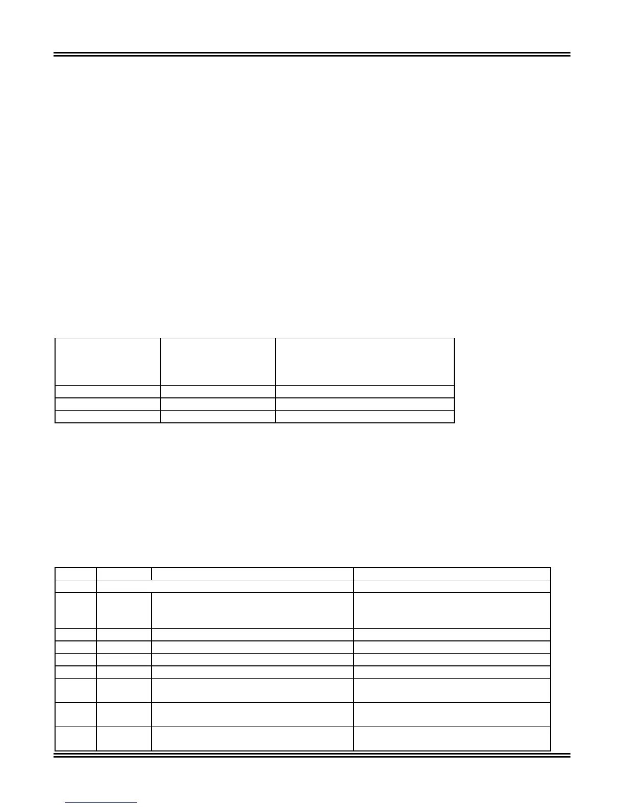
A Truth Table for the aforementioned bits follows as illustrated in Table 5-50:
Table 5-50. State Truth Chart for Physical Input Forcing Function
Bit Value
Change Mask
Register 41444
through 41447
Bit Value
Normal/Forced Mask
Register 41448
through 41451
Description
0 X Normal - State Unforced
1 0 Logical Input Forced – State = OFF
1 1 Logical Input Forced – State = ON
There are three modes which a Physical Output may be placed:
• UNFORCED – The TPU2000/TPU2000R Logical Input is not forced to any state.
• SET – The TPU2000/TPU2000R bit is set to a value of 1.
• RESET -The TPU2000/TPU2000R is set to a value of 0.
It should be noted that certain bits within the table can only be reset when selected. Other bits may be set or
reset at will. Once a bit is forced, the NORMAL LED (located at the faceplate of the TPU2000 and 2000R) shall
flash. The Normal LED is green in color.
Table 5-51. TPU2000 and TPU2000R Bit Control Function Definitions
Notes Register Item Description
GROUP V
41440 Execute Register
0 = No Action
1 = Execute
Unsigned (16 Bits)
41441 Password ASCII – 2 Characters Leftmost Digits
41442 Password ASCII – 2 Characters Rightmost Digits
41443 Spare
41444 Change Mask Register 1
R
Bit 15: 87T - 3 % Phase Differential
Current Alarm
1 = Select bit 0 = Normal (msb)
R
Bit 14: 87H - 3 Instantaneous Phase
Differential Current Alarm
1 = Select bit 0 = Normal
R
Bit 13: 2HROA - Second Harmonic
Restraint Alarm
1 = Select bit 0 = Normal
 Loading...