TPU2000/2000R Modbus/Modbus Plus Automation Guide
143
E
C
Command
Sequence Through
Modbus Command 16
Preset Multiple Holding Registers
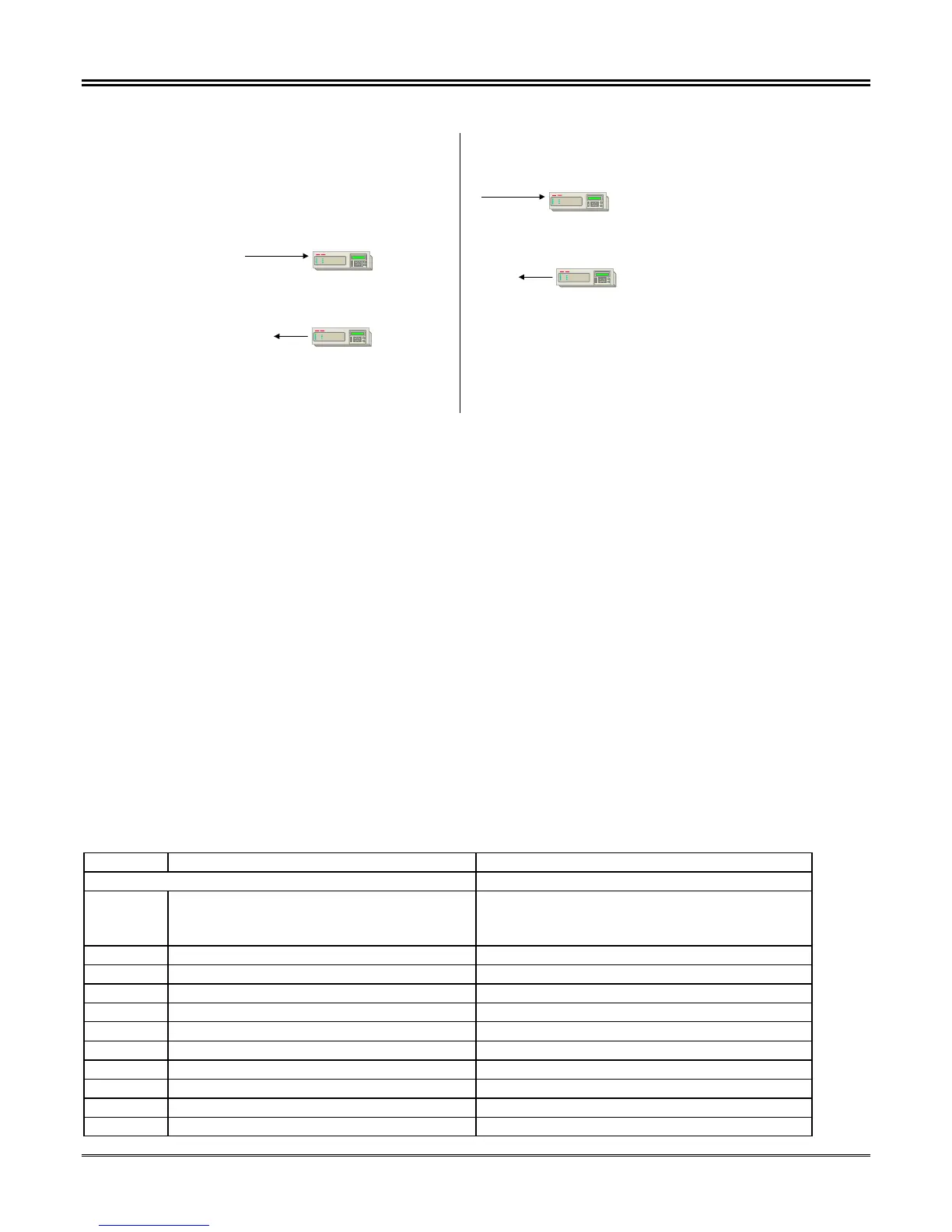
STEP 5 -
Host sends following register contents
to initiate Force Physical Input 4 Normal ( Assumed that
default password of all spaces is active).
41417 = 2020 hex (Password Hi)
41418 = 2020 hex (Password Lo)
41419 = 0 (Reserved)
41420 = 0008 hex (Select Bit to Change)
41421 = 0000 hex ( Place Bit in Normal “Unforced” State).
41422 = 0000 hex ( Send State of Force = Don’t Care)
EXAMPLE 2 - Force Input 4 to a State of 1 and Then to a Force State of 0, and
Then to a Normal State.
E
C
The relay reports the Input Status of Physical Input 1 to be
that reflected at the Physical Input terminals of the TPU 2000R.
A Modbus response will be returned to the host
indicating that the command has been accepted.
E
C
Command
Sequence Through
Modbus Command 16
Preset Multiple Holding Registers
STEP 6 -
The host sends the register execute
command to the following address
with the following contents.
41416 = 0001 hex
E
C
The Relay Responds
over the network that
the command has been
accepted.
Figure 5-50. Force Physical Input Example (Continued)
IMPLEMENTATION TIP –As is common practice with any control, after a control task has been completed via the
network, the host should query the device to assure that control has been executed.
Group III Control Features Explained
The complimentary control functions are available for forcing the Physical Output contacts located at the back of
the relay. The Physical Output force functions follows that of the Physical Input Force Functionality. There are
three modes which a Physical Output may be placed:
• NORMAL – The TPU2000R Physical Output reflects that of the logic configured within the protective
relay
• FORCED ON – The TPU2000R Physical Output is energized. The Physical Output status is reported
as a 1. If the point status is viewed via ECP or WinECP, the point will show a forced status
• FORCED OFF –TPU2000R Physical Output is de-energized. The Physical Output status is reported
as a 0. If the point status is viewed via ECP or WinECP, the point will show a forced status.
Table 5-45 illustrates the mapping for Physical Output Forcing Capabilities.
Table 5-45. TPU2000R Bit Control Function Definitions
Register Item Description
GROUP III
41423 Execute Register
0 = No Action
1 = Execute
Unsigned (16 Bits)
41424 Password ASCII – 2 Characters Leftmost Digits
41425 Password ASCII – 2 Characters Rightmost Digits
41426 Spare
41427 Force Physical Output Change Mask Unsigned (16 Bits)
Bit 0 Trip (Terminal 29,30) (lsb) 1 = Control Bit State 0 = No Control
Bit 1 Output 1 (Terminal 28,27) 1 = Control Bit State 0 = No Control
Bit 2 Output 2 (Terminal 26,25) 1 = Control Bit State 0 = No Control
Bit 3 Output 3 (Terminal 24,23) 1 = Control Bit State 0 = No Control
Bit 4 Output 4 (Terminal 22 21) 1 = Control Bit State 0 = No Control
Bit 5 Output 5 (Terminal 19,20) 1 = Control Bit State 0 = No Control
 Loading...