EasyManua.ls Logo

Acer Aspire V3-471 User Manual

Acer Aspire V3-471
333 pages
To Next Page IconTo Next Page
To Previous Page IconTo Previous Page
Page #132 background imageLoading...
Page #132 background image
3-38 Machine Maintenance Procedures
Support Bracket Removal 0
Prerequisite:
LCD (Liquid Crystal Display) Module Removal
1. Find Support Brackets (B) on the base assembly. Refer to Figure 3-36.
2. Remove four (4) screws securing the support brackets in place (Figure 3-36).
3. Remove the support brackets from the base assembly.
Figure 3-36. Support Brackets
Support Bracket Installation 0
1. Place the support brackets (B) on the base assembly. Refer to Figure 3-36
2. Install and secure four (4) screws to the support brackets (Figure 3-36).
3. Install LCD Module.
ID Size Quantity Screw Type
AM2.5*4 4
A
A
B
B

Table of Contents

Question and Answer IconNeed help?

Do you have a question about the Acer Aspire V3-471 and is the answer not in the manual?

Acer Aspire V3-471 Specifications

General IconGeneral
Optical DriveDVD-Super Multi DL drive
ProcessorIntel Core i3/i5/i7 (depending on model)
RAM4GB DDR3
Storage500GB HDD
Display14-inch HD (1366x768)
GraphicsIntel HD Graphics 3000
Operating SystemWindows 7 Home Premium
Battery6-cell Li-ion
Weight2.1 kg
Dimensions342 x 245 x 25.4 mm
PortsHDMI, VGA, Ethernet, headphone/microphone combo jack
Wireless802.11b/g/n

Summary

CHAPTER 1 Hardware Specifications

CPU

Details on the central processing unit models and specifications.

System Memory

Information on system memory type, size, and socket details.

CHAPTER 2 System Utilities

BIOS Setup Utility

Guide to accessing and navigating the BIOS setup utility for hardware configuration.

Clearing BIOS Passwords

Steps to clear or remove Insyde HDD/BIOS passwords for system access.

CHAPTER 3 Machine Maintenance Procedures

Mainboard Removal

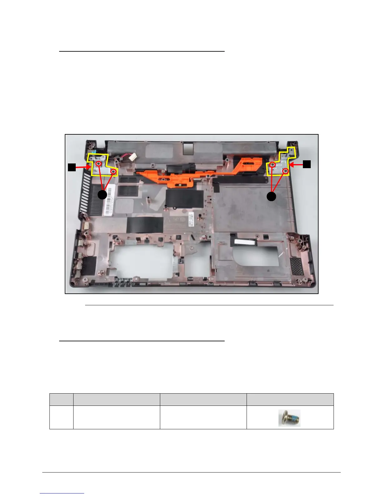
Step-by-step guide for removing the main system board.

CHAPTER 4 Troubleshooting

Power On Issues

Troubleshooting steps for when the system does not power on.

No Display Issues

Steps to resolve problems where the display does not work or show POST.

CHAPTER 6 FRU (Field Replaceable Unit) List

FRU List

Comprehensive list of Field Replaceable Units with part numbers.

CHAPTER 8 Test Compatible Components

Microsoft® Windows® 7 Environment Test

List of components verified for compatibility with Windows® 7 environment.

Related product manuals