329
Chapter 7 Tutorial
Pulse Waveform Generation
4
7
Pulse Waveform Generation
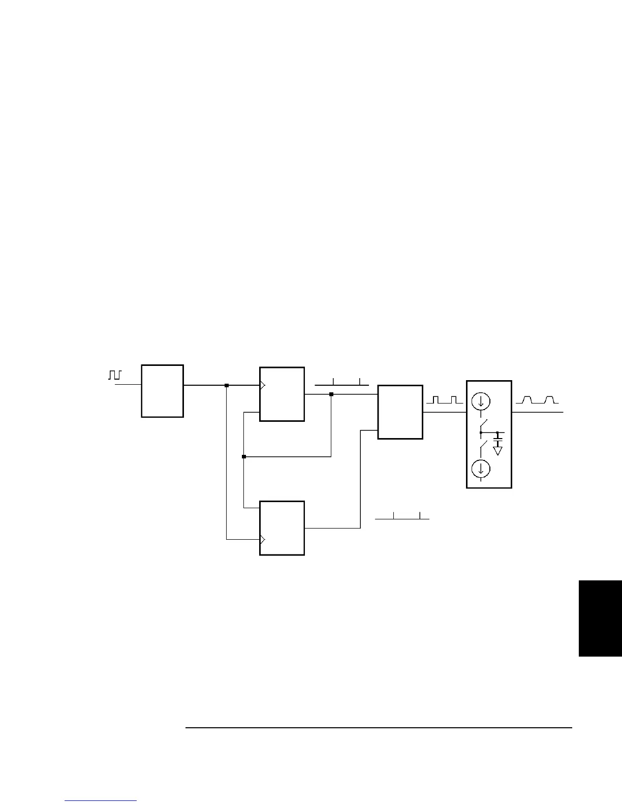
To eliminate distortion due to aliasing at higher frequencies, the Agilent
33220A also uses a different waveform generation technique to create
pulse waveforms. For pulse waveform generation, clock cycles are
counted to derive both the period and the pulse width. To achieve fine
period resolution, the clock frequency is varied from 95 to 100 MHz by a
phase lock loop (PLL) circuit (which also multiplies the incoming
frequency from the DDS by five). The rising and falling edge times are
controlled by a circuit that varies the charging currents in a capacitor.
Period, pulse width, and edge time are controlled independently, within
certain limits. The pulse waveform generation circuitry is represented in
the following block diagram.
Pulse Waveform Generation Circuitry
From DDS
Phase
Lock
Loop
(x5)
Load
Period
Counter
95 - 100 MHz
Leading Edge
Edge Time
Circuit
Set
Clear
Flip/Flop
Trailing Edge
Load
Width
Counter

 Loading...


