332
Chapter 7 Tutorial
Output Amplitude Control
7
Output Amplitude Control
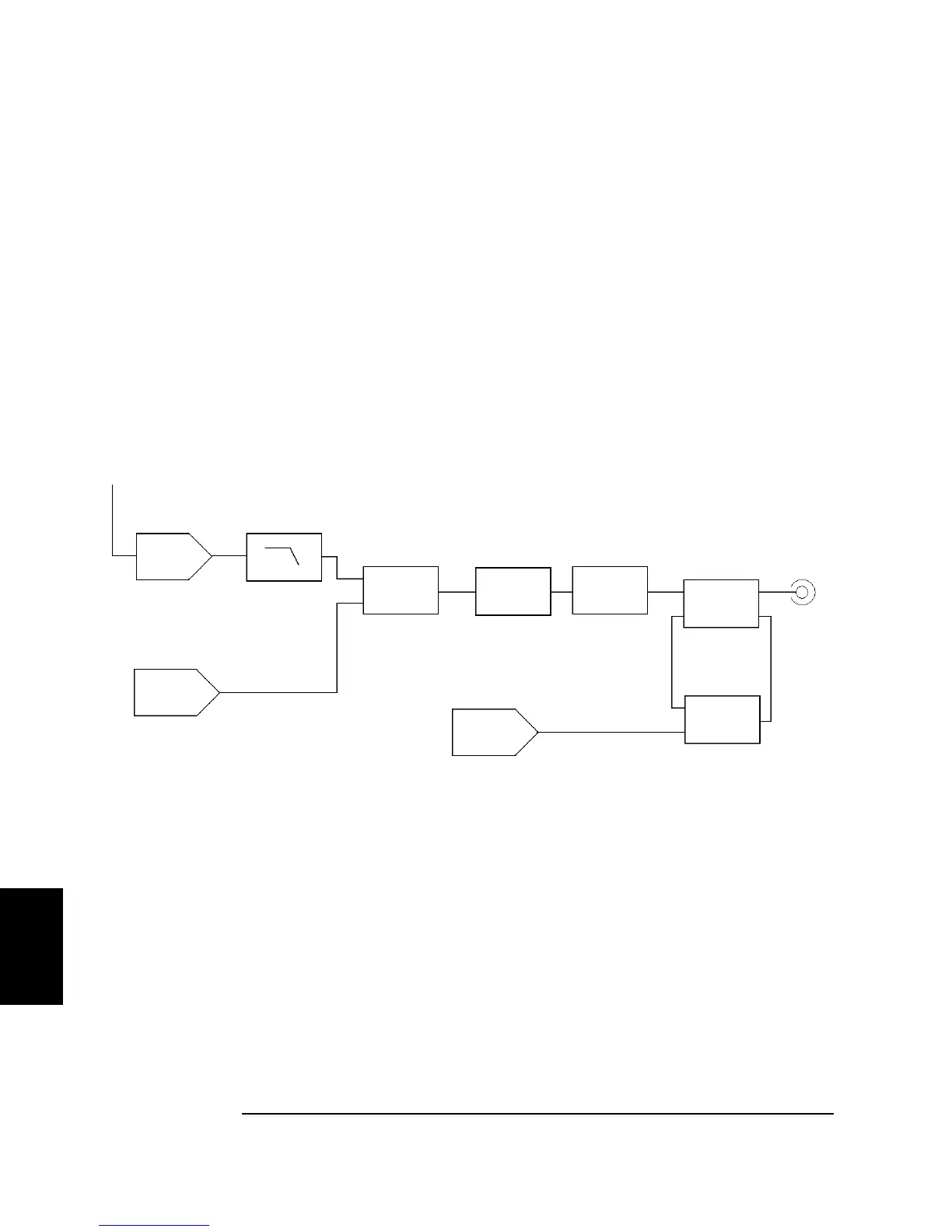
The Agilent 33220A uses a variable reference voltage to control the
signal amplitude over a 10 dB range. As shown in the simplified block
diagram below, the output of the waveform DAC goes through an anti-
aliasing filter. Switching circuitry selects either the waveform output or
the output of the separate square/pulse DAC. Two attenuators (-10 dB
and -20 dB) are used in various combinations to control the output
amplitude in 10-dB steps over a wide range of amplitude values
(10 mVpp to 10 Vpp)
.
Note that the dc offset is summed with the ac signal in the output
amplifier. This allows relatively small ac signals to be offset by relatively
large dc voltages. For example, you can offset a 100 mVpp signal by
almost 5 Vdc (into a 50Ω load).
When changing ranges, the 33220A switches attenuators such that the
output voltage never exceeds the current amplitude setting. However,
momentary disruptions or "glitches" caused by switching can cause
problems in some applications. For this reason, the 33220A incorporates
a range hold feature to "freeze" the attenuator and amplifier switches in
their current states. However, the amplitude and offset accuracy and
resolution (as well as waveform fidelity) may be adversely affected when
reducing the amplitude below the expected range change.
Variable
Vref
Waveform
DAC
Anti-Aliasing
Filter
Switching
Circuitry
Attenuators
0 dB or
-10 dB
0 dB or
-20 dB
Switching
Circuitry
Main
Outpu
Output
Amplifier
0 dB or
+20 dB
DC Offset
DAC
Square/Pulse
DAC

 Loading...


