40
Chapter 2 Front-Panel Menu Operation
To Output a PWM Waveform
2
To Output a PWM Waveform
You can configure the function generator to output a pulse width
modulated (PWM) waveform. The Agilent 33220A provides PWM for
pulse carrier waveforms, and PWM is the only type of modulation
supported for pulse waveforms. In PWM, the pulse width or duty cycle of
the carrier waveform is varied according to the modulating waveform.
You can specify either a pulse width and width deviation, or a pulse duty
cycle and duty cycle deviation, the deviation to be controlled by the
modulating waveform.
For this example, you will specify a pulse width and pulse width
deviation for a 1 kHz pulse waveform with a 100 Hz sine wave
modulating waveform.
1 Select the carrier waveform parameters.
Press and then press the Freq, Ampl, Offset, Width, and Edge
Time softkeys to configure the carrier waveform. For this example, select
a 1 kHz pulse waveform with an amplitude of 1 Vpp, a zero offset, a pulse
width of 100 µs, and an edge time of 50 ns.
2 Select PWM.
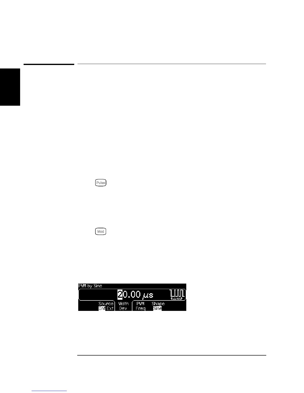
Press (PWM is the only modulation type for Pulse). Notice that a
status message "PWM by Sine" is shown in the upper-left corner of the
display.
3 Set the width deviation.
Press the Width Dev softkey and set the value to 20 µs using the numeric
keypad or the knob and cursor keys.

 Loading...


