238
Chapter 4 Remote Interface Reference
Arbitrary Waveform Commands
4
• The following statement shows how to use the DATA:DAC command to
download seven integer points using the binary block format (see also
“Using the IEEE-488.2 Binary Block Format” below).
DATA:DAC VOLATILE, #214
Binary Data
• The following statement shows how to use the
DATA:DAC
command to
download five integer points in decimal format.
DATA:DAC VOLATILE, 8191, 4096, 0, -4096, -8191
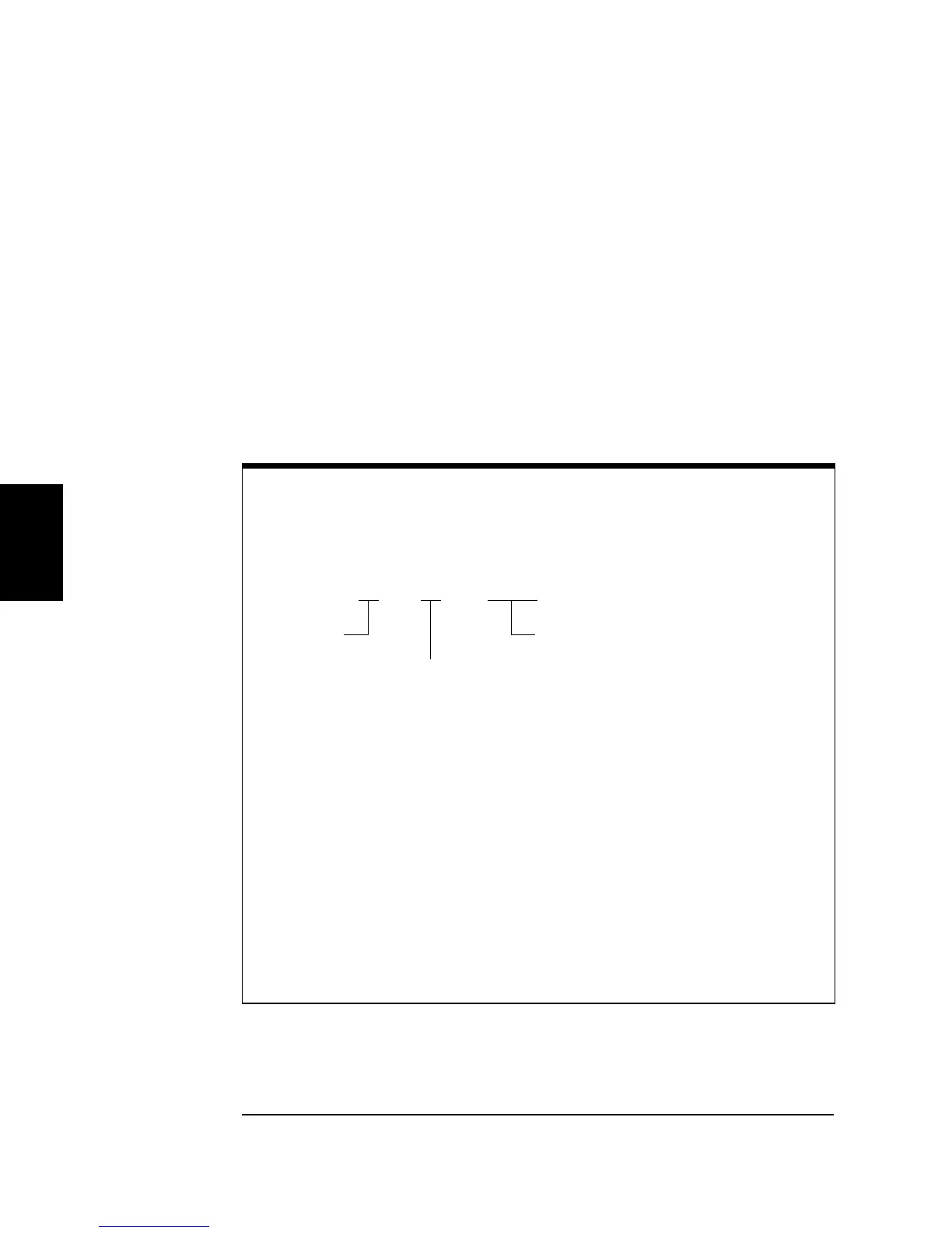
Using the IEEE-488.2 Binary Block Format
In the binary block format, a block header precedes the waveform data.
The block header has the following format:
#532768
The function generator represents binary data as 16-bit integers, which
are sent as two bytes. Therefore,
the total number of bytes is always
twice the number of data points in the waveform
(and must always be an
even number). For example, 32,768 bytes are required to download
a waveform with 16,384 points.
Use the FORM:BORD command to select the byte order for binary
transfers in block mode. If you specify FORM:BORD NORM (default),
the most-significant byte (MSB) of each data point is assumed first.
If you specify FORM:BORD SWAP, the least-significant byte (LSB) of
each data point is assumed first. Most computers use the “swapped”
byte order.
Start of
Data Block
Number of Digits
to Follow
Even Number of Bytes to Follow
(32,768 bytes = 16,384 points)