EasyManuals Logo
Home>Agilent Technologies>Switch>34970A

Agilent Technologies 34970A Service Guide

Agilent Technologies 34970A
273 pages
To Next Page IconTo Next Page
To Previous Page IconTo Previous Page
Page #104 background imageLoading...
Page #104 background image
(Optional)
34904A Relay Contact Resistance Verification
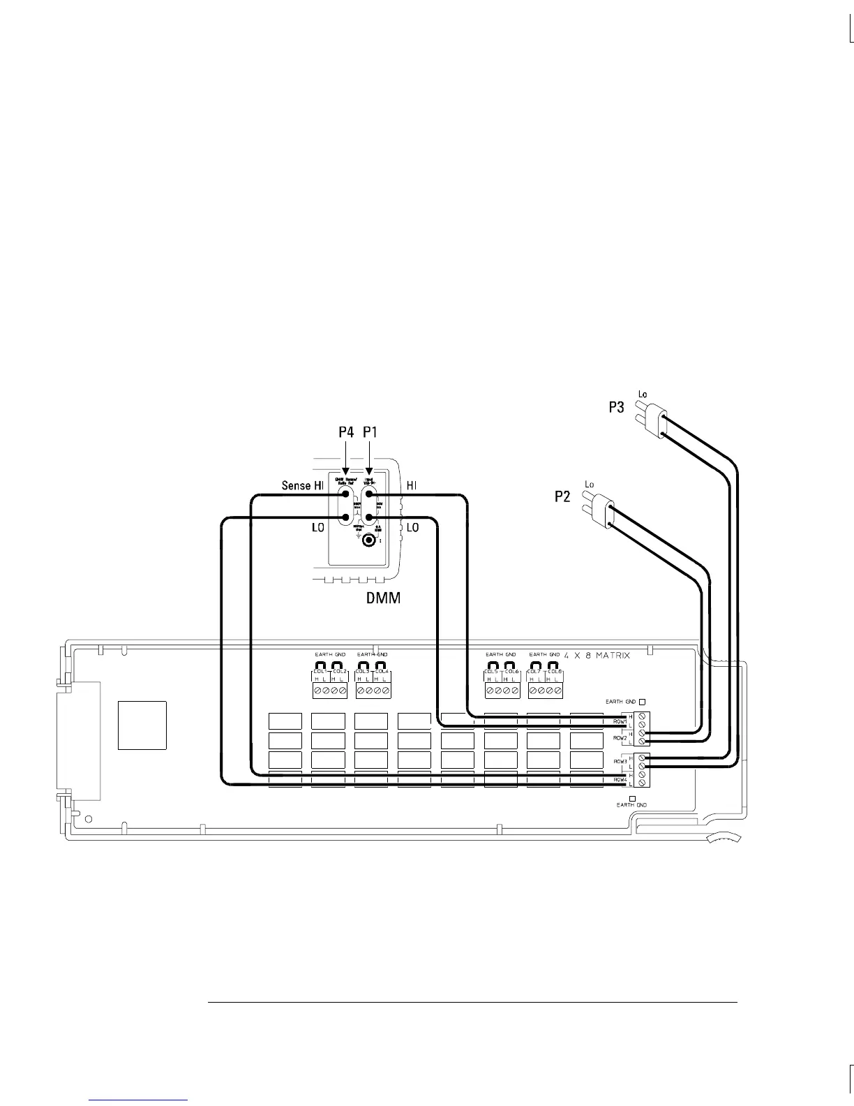
This optional procedure uses an external DMM to make 4-wire ohms
measurements across the relay contacts on the 34904A.
1 Be sure to read “Plug-in Module Test Considerations on page 87.
2 Connect coppers shorts from H to L on each of the eight columns
(COL1 through COL8) as shown below. Connect four dual banana
plugs to the four rows as shown below (ROW1 through ROW4).
Be sure to route your wiring for proper strain relief and install the
module cover. Install the 34904A in slot 200 of the 34970A.
Connections for 34904A Verification Tests
Chapter 4 Calibration Procedures
Relay Verification
102

Table of Contents

Other manuals for Agilent Technologies 34970A

Questions and Answers:

Question and Answer IconNeed help?

Do you have a question about the Agilent Technologies 34970A and is the answer not in the manual?

Agilent Technologies 34970A Specifications

General IconGeneral
BrandAgilent Technologies
Model34970A
CategorySwitch
LanguageEnglish

Related product manuals