(Optional)
34901A Relay Contact Resistance Verification
This optional procedure uses an external DMM to make 4-wire ohms
measurements across the relay contacts on the 34901A. The measured
resistance is the series resistance of the two relay contacts (both
contacts are in the same relay).
Note: Be sure to read “Plug-in Module Test Considerations” on page 87.
Tests 1 - 5: See the diagram on page 90 for the required connections for each test
(be sure to probe the components at the indicated location). For these
measurements, the 34901A is not installed in the 34970A. Record the
4-wire ohms measurements from the external DMM in the table below.
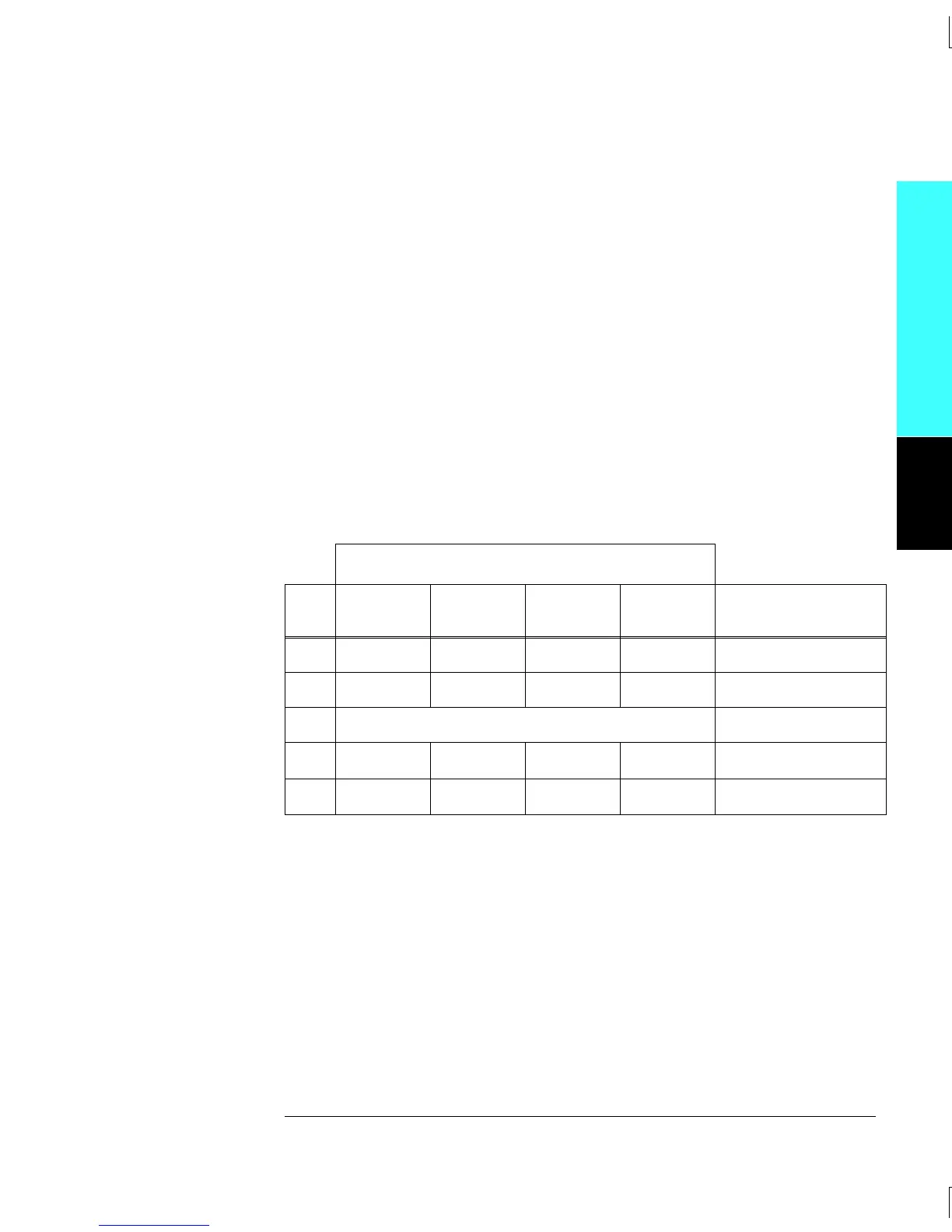
Note: The connections to the external DMM are different for each of
Tests 1, 2, 4, and 5. Be sure to verify the connections shown in the
table below for each of the four tests.
External DMM Ohmmeter Connections
Test
#
HI LO
HI
Sense
LO
Sense
Measured
Value
1 L401 J101, C14 L401 J101, C14 __________ Ohms
2 L402 J101, C15 L402 J101, C15 __________ Ohms
3 Add (Test 1 + Test 2) __________ Ohms
4F501
Ch 21 I
F501
Ch 21 I
__________ Ohms
5F502
Ch 22 I
F502
Ch 22 I
__________ Ohms
Module Reference
4
Chapter 4 Calibration Procedures
Relay Verification
89

 Loading...

