EasyManuals Logo
Home>Agilent Technologies>Switch>34970A

Agilent Technologies 34970A Service Guide

Agilent Technologies 34970A
273 pages
To Next Page IconTo Next Page
To Previous Page IconTo Previous Page
Page #92 background imageLoading...
Page #92 background image
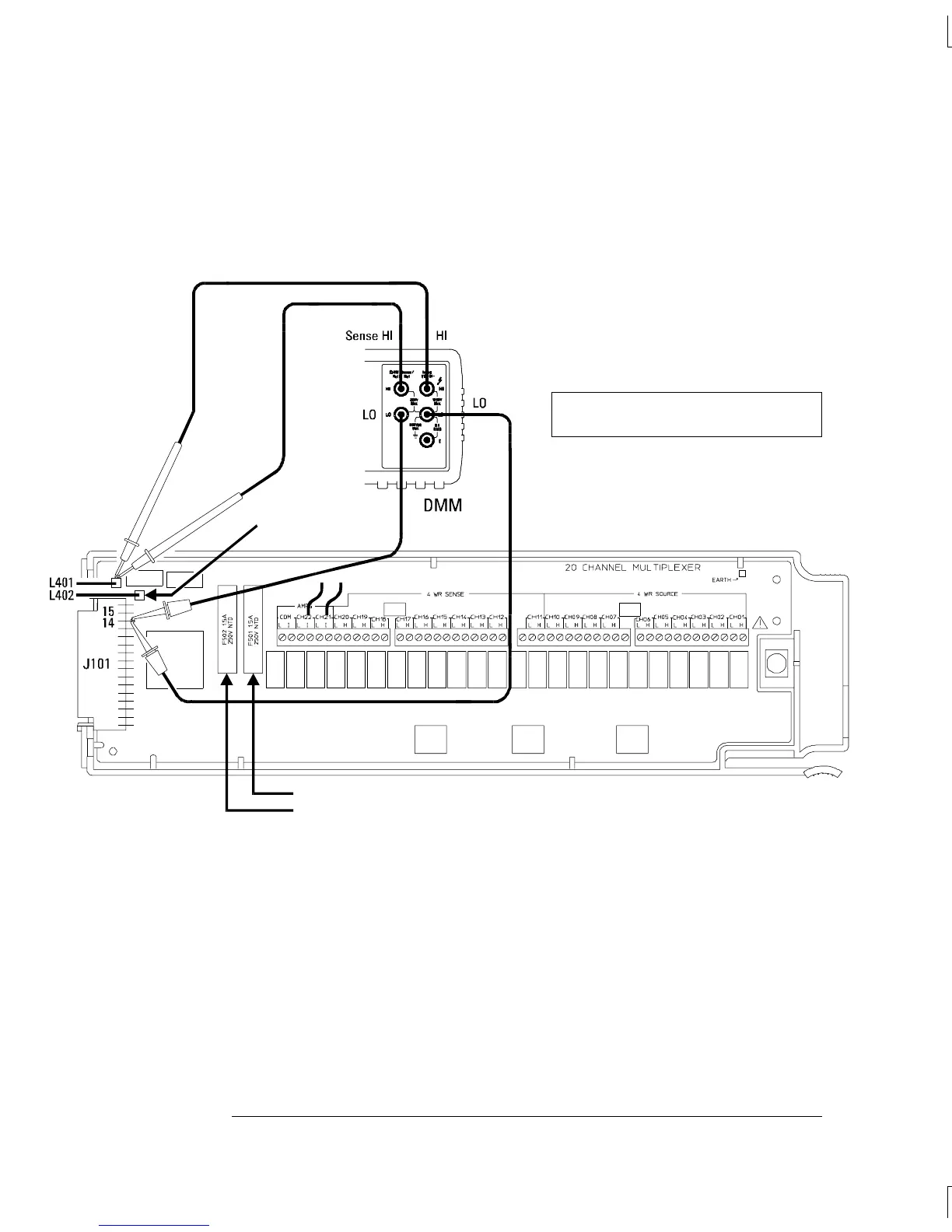
Note: Connect bare copper wires (approximately 3 cm in length)
to the I terminals of Channels 21 and 22 as shown below. These wires
will be used to make shorts across the channels in Tests 6 through 39.
Probe here for F501 measurement.
Probe here for F502 measurement.
Probe here
for L402
measurement.
Connections for 34901A Verification Tests 1 through 5
Note: Be sure to probe the components
at the indicated locations on the module.
Chapter 4 Calibration Procedures
Relay Verification
90

Table of Contents

Other manuals for Agilent Technologies 34970A

Questions and Answers:

Question and Answer IconNeed help?

Do you have a question about the Agilent Technologies 34970A and is the answer not in the manual?

Agilent Technologies 34970A Specifications

General IconGeneral
BrandAgilent Technologies
Model34970A
CategorySwitch
LanguageEnglish

Related product manuals