EasyManuals Logo
Home>Agilent Technologies>Switch>34970A

Agilent Technologies 34970A Service Guide

Agilent Technologies 34970A
273 pages
To Next Page IconTo Next Page
To Previous Page IconTo Previous Page
Page #140 background imageLoading...
Page #140 background image
Switch Modules
In general, all the switch modules share a common module control
circuitry. This circuitry is described below. Each module is described
in further detail on the following pages.
Switch Module Name Page
34901A 20 Channel MUX with T/C Compensation 142
34902A 16 Channel Reed MUX with T/C Compensation 144
34903A 20 Channel Actuator 146
34904A 4 X 8 Matrix Switch 147
34905A
50 Dual 4:1 VHF MUX
148
34906A
75 Dual 4:1 VHF MUX
148
34908A 40 Channel Single-Ended MUX with T/C Compensation 149
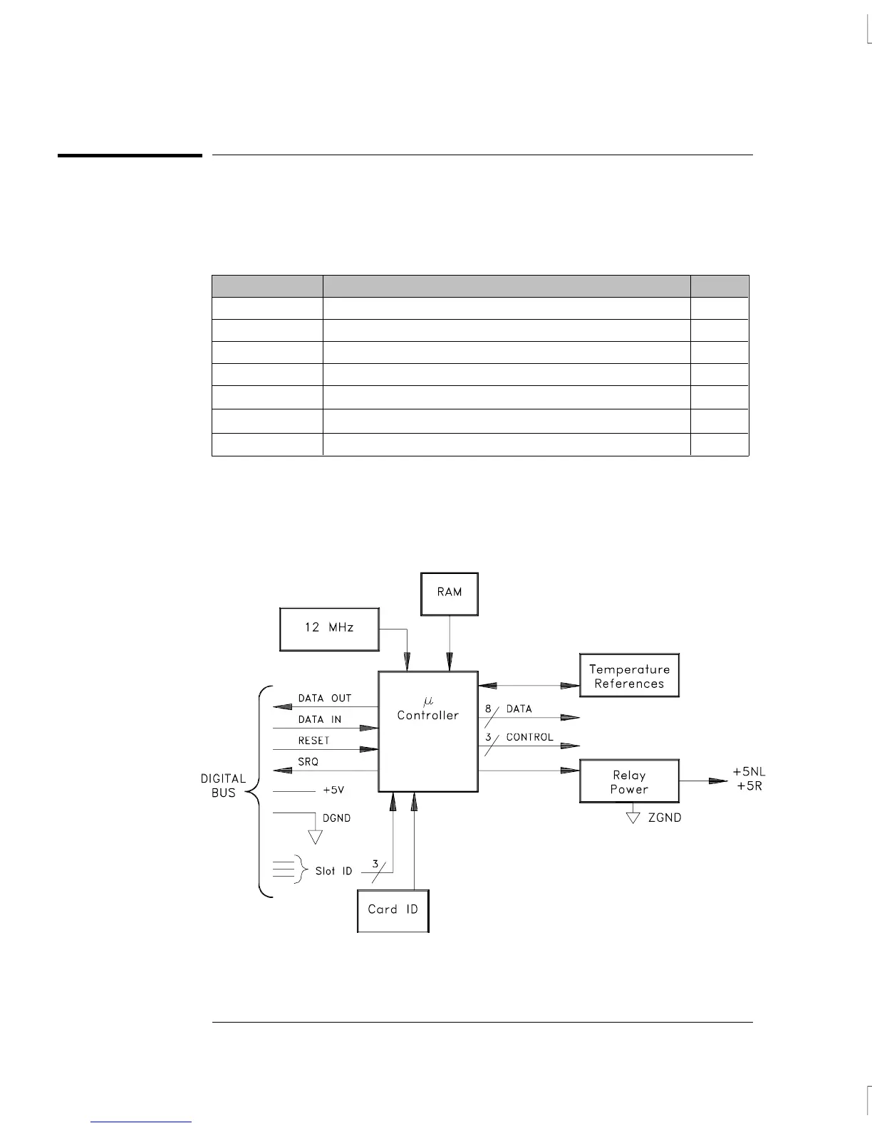
Switch Module Control
A simplified block diagram of a typical module controller is shown below.
Chapter 5 Theory of Operation
Switch Modules
138

Table of Contents

Other manuals for Agilent Technologies 34970A

Questions and Answers:

Question and Answer IconNeed help?

Do you have a question about the Agilent Technologies 34970A and is the answer not in the manual?

Agilent Technologies 34970A Specifications

General IconGeneral
BrandAgilent Technologies
Model34970A
CategorySwitch
LanguageEnglish

Related product manuals