Thermocouple Reference Junction Adjustments
These adjustments are plug-in module specific and only affect thermo-
couple measurements. The calibration constants created by these
adjustments are stored in non-volatile memory on the plug-in module.
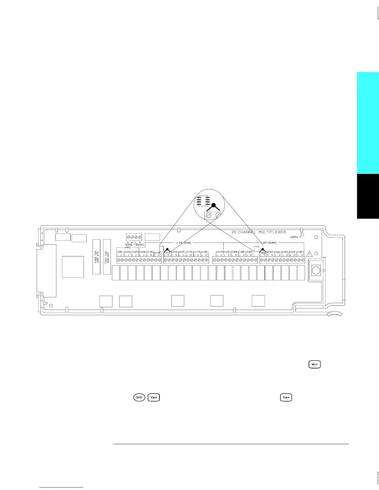
1 Connect a 10 kΩ (YSI 44031) thermistor to each of the following channels
(a kit of five thermistors is available as Agilent part number 34308A):
For the 34901AChannels 6 and 17
For the 34902AChannels 6 and 11
For the 34908AChannels 6 and 16
Keep the thermistor leads as short as possible. Locate the thermistor
as near to the input connectors as possible.
2 Install the plug-in module in the mainframe in slot 200. Apply power
and allow a 2 hour warm-up.
3 Set 10 kΩ thermistor measurements on Channels 206 and 217
(or 206 and 211). Before executing each test, you must press
to enable reading monitoring on the selected channel (or use the
ROUTe:MON command from the remote interface).
4
Press to enter the calibration menu. Press again to
begin the adjustment procedure.
5 Verify the adjustment (see page 112).
Module Reference
34901A
4
Chapter 4 Calibration Procedures
Thermocouple Reference Junction (Optional)
113

 Loading...

