Input
Unless otherwise noted, components in this discussion are located on
the A4 circuit assembly (34970-66504). The schematics are included
in Chapter 8 starting on page 234.
The purpose of the Input section is to connect the
Input HI terminal to
the various measuring functions. This is accomplished through K102,
K103, and K104. Additionally, connections are made for the 4-wire
ohms
HI Sense and LO Sense inputs. Shunt selection (ranging) and
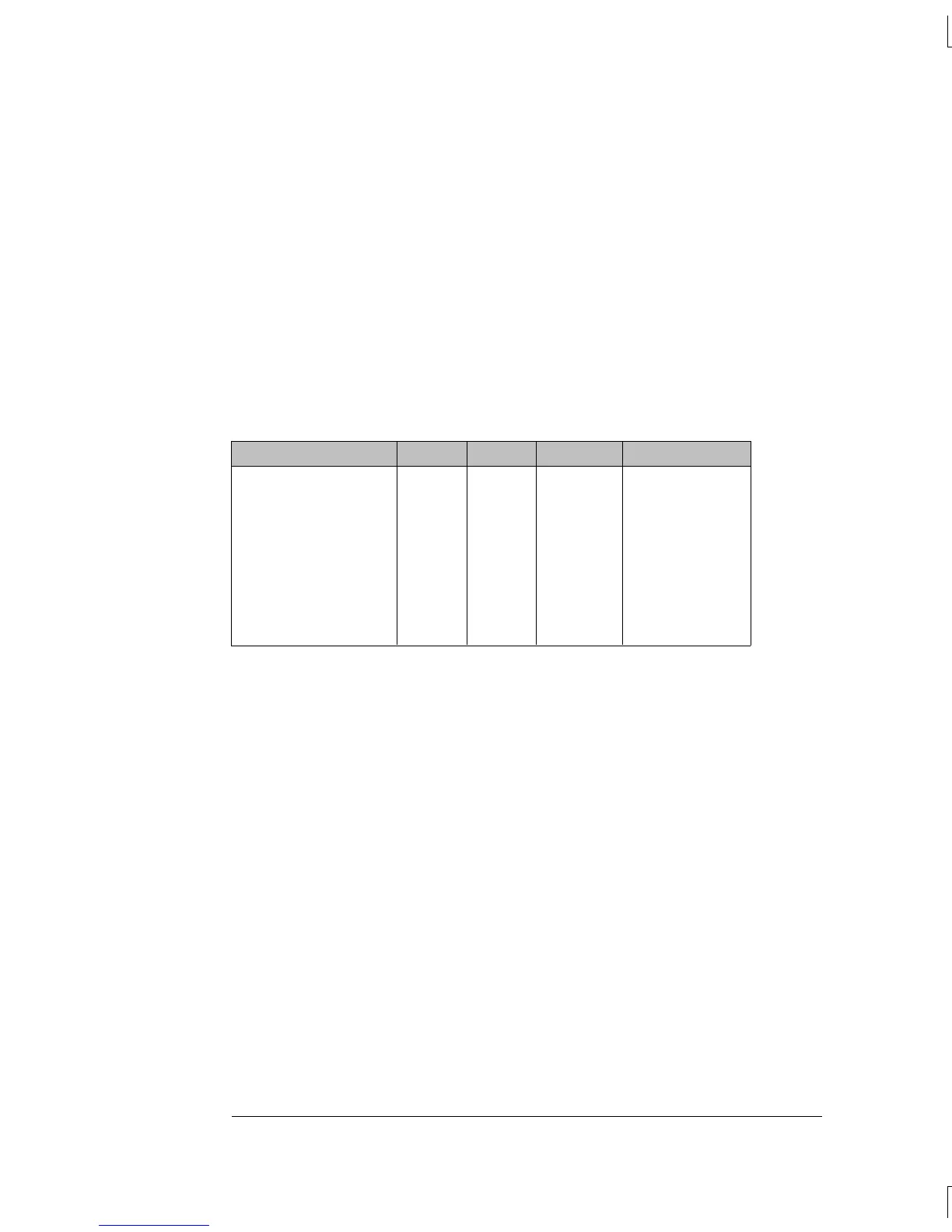
voltage sensing are also performed for the current function. The table
below shows the state of each relay for each measuring function.
All relay coils are driven from U150.
Function K102 K103 K104 Sense at:
0.1 V – 10 Vdc
100 V – 300 Vdc
2-Wire Ohms
4-Wire Ohms
AC Voltage
Frequency/Period
3 A, 1A DC I
100 mA, 10 mA DC I
1A AC I
Set
Set
Reset
Reset
Set
Set
Reset
Set
Reset
Set
Reset
Set
Set
Reset
Reset
Reset
Reset
Reset
Set [1]
Set
Reset [2]
Reset [2]
Reset
Reset
Reset
Reset
Set
U101-5
U102-12
U101-5
[3]
AC_IN
AC_IN
U101-10
U101-10
AC_IN
[1] K104 will be reset when input resistance is selected to >10,000 MΩ through the menu.
[2] K104 will be set for the 100 M
Ω range.
[3] Configurations shown are for the current source output (HI) terminal. The measurement
sense is accomplished through the Sense HI / Sense LO terminals.
Chapter 5 Theory of Operation
Internal DMM
130

 Loading...

