Backplane
Unless otherwise noted, components in this discussion are located
on the A3 circuit assembly (34970-66503). The schematics are
included in Chapter 8 starting on page 231.
The backplane contains three connectors, P101, P102, and P103 for
connection to the plug-in modules. The parallel lines in these
connectors are divided into two groups to form the analog bus and
digital bus.
Analog Bus
The analog bus connects the signals from the plug-in modules to the
Internal DMM. There are five lines in the analog bus, HI, LO,
OHMS_HI, OHMS_LO, and AMPS. The HI and LO lines are
protected from overvoltages by E101, E102, RV101, RV102, R101,
R160, L101, L102, and C109.
P105 makes the analog bus connection to the internal DMM.
Digital Bus
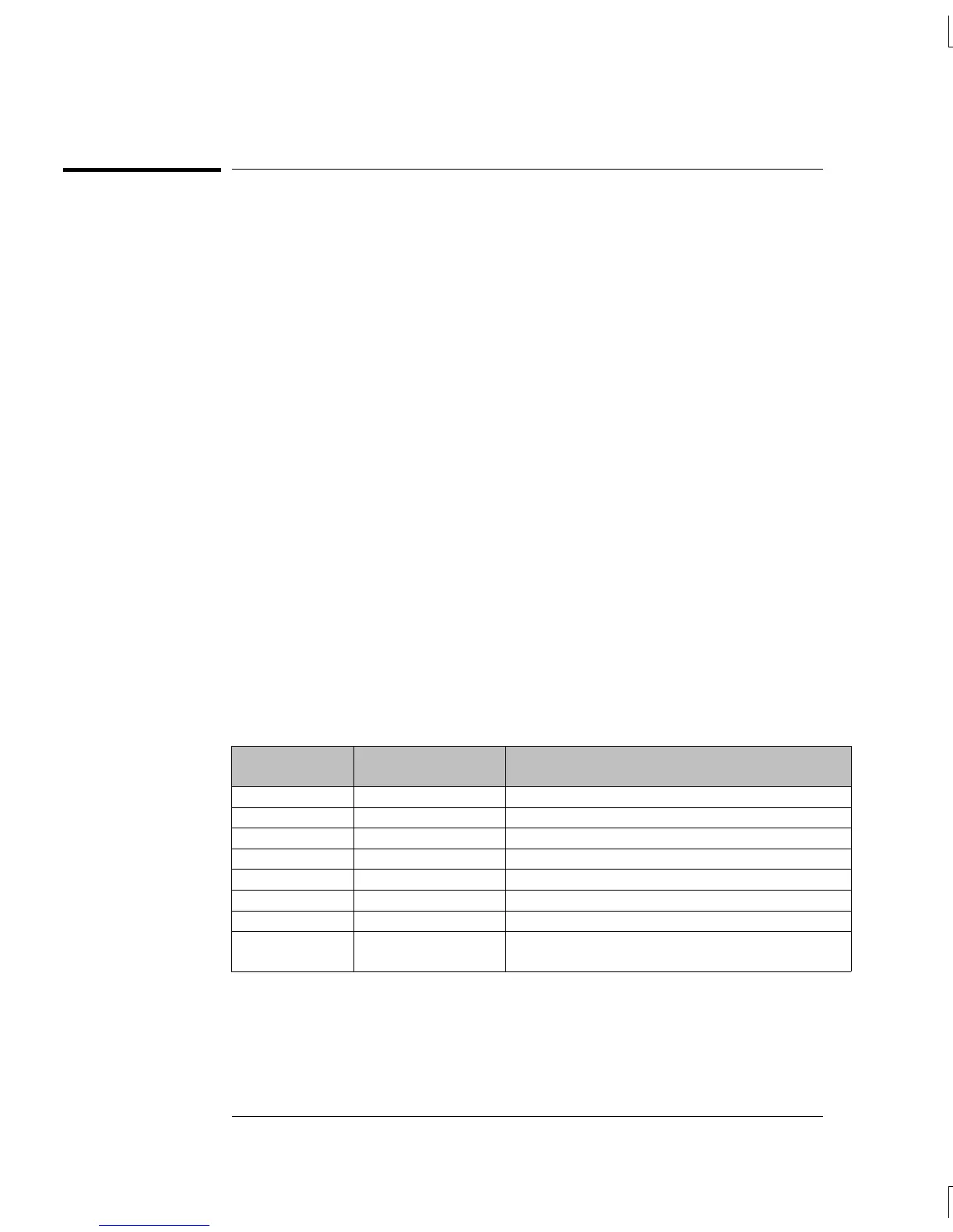
The digital bus uses 10 lines for communication and control. P104
makes the digital bus connection to the earth referenced logic and
floating logic.
Signal
P101, P102, P103
Pins
Comments
Slot ID A6, A7, A8 Unique binary code for each slot.
DATA_IN B6 Serial module data from the floating logic.
DATA_OUT C6 Serial module data to the floating logic.
DGND A5, B5, B7, C5, C7 Earth referenced digital ground.
+5 V A3, B3, C3 Earth referenced module power supply.
Earth Ground A1, B1, C1 Earth referenced zap return ground.
RST B8 Module reset from the earth referenced logic.
SRQ C8 Module service request to the earth
referenced logic.
Chapter 5 Theory of Operation
Backplane
128

 Loading...

