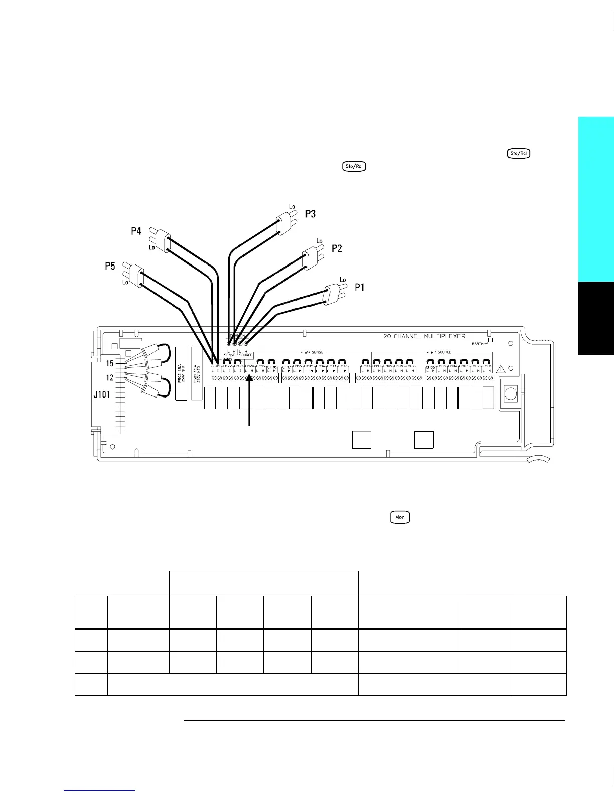
Tests 6 - 8: Make the connections to the 34901A as shown in the diagram below.
Be sure to route your wiring for proper strain relief and install the
module cover. Install the 34901A in slot 200 of the 34970A. Open all
channels on the module by performing a Factory Reset (press
and select “Recall State”; press again and select “Factory Reset”).
Configure Channel 20 as follows: DC volts, 10 volt range, and 5
1
⁄
2
digits.
Enable reading monitoring by pressing on the selected channel
(or use the ROUTe:MON command). Record the 4-wire ohms
measurements from the external DMM in the following table.
External DMM Ohmmeter Connections
Test
#
Channel
Configured
HI LO
HI
Sense
LO
Sense
Measured Value
Test
Limit
Relay
Measured
6 Ch 20 P2 P2 P1 P1 __________ Ohms
2.00Ω
K421
7 Ch 20 P2 P2 P3 P3 __________ Ohms — —
8 Subtract (Test 7 – Test 6) __________ Ohms
2.00Ω
K422
Module Reference
Connections for 34901A Verification Tests 6 through 39
Channel 20 should be left open.
4
Chapter 4 Calibration Procedures
Relay Verification
91

 Loading...

