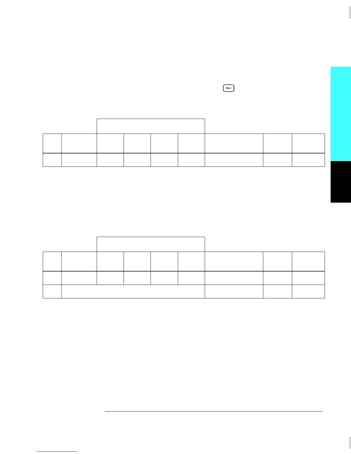
Test 37: Install the 34901A in slot 200 of the 34970A. Select and configure
Channel 21 as follows: DC current, 1 amp range, and 5
1
⁄
2
digits.
Enable reading monitoring by pressing on the selected channel
(or use the ROUTe:MON command). Record the 4-wire ohms
measurement from the external DMM in the following table.
External DMM Ohmmeter Connections
Test
#
Channel
Configured
HI LO
HI
Sense
LO
Sense
Measured Value
Test
Limit
Relay
Measured
37 Ch 21 P4 P4 P5 P5 __________ Ohms
2.00Ω
K521
Tests 38 - 39: Open all channels on the module by performing a Factory Reset.
Close Channel 21 (module in slot 200). Remove the 34901A from the
34970A and do not reinstall it for the remaining tests. Using the
external DMM, make a 4-wire ohms measurement between the L
and I terminals on Channel 22. Record the measured value as Test 38 in
the following table.
External DMM Ohmmeter Connections
Test
#
Channel
Closed
HI LO
HI
Sense
LO
Sense
Measured Value
Test
Limit
Relay
Measured
38 Ch 21
Ch 22 I
Ch 22 L
Ch 22 I
Ch 22 L __________ Ohms — —
39 Subtract (Test 38 – Test 5) __________ Ohms
2.00Ω
K524
Module Reference
4
Chapter 4 Calibration Procedures
Relay Verification
95

 Loading...

