292 Chapter 9
BERT
Bit Error Rate Tester–Option UN7
Gate Delay Function in the Clock Mode
To use this function, the clock must be set to continuous mode.
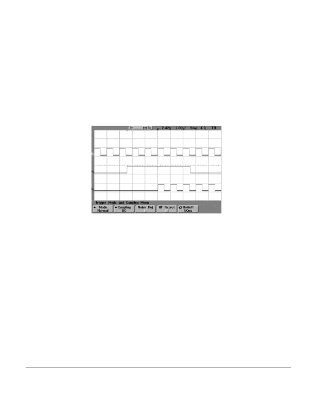
In this example, the clock is used to delay the gate function. The clock of the internal error detector was
gated by the gate signal which is delayed by two clocks. Figure 9-23 shows that CH0 and CH1 are the input
of the clock and data from the rear panel input connectors of UN7. CH2 is the gated clock through the AUX
I/O connector.
Figure 9-23
CH0: BER CLK IN (rear panel SMB connector)
CH1: BER GATE IN (rear panel SMB connector)
CH2: BER TEST OUT (pin 20 of AUX I/O connector)
Triggering
This section describes the operating principles of the triggering function for Option UN7. To see the signal
flow of the triggering function refer to Figure 9-24.
CH1
CH2
CH0

 Loading...


