Chapter 1 17
E4428C Analog Signal Generator Overview
Rear Panel Overview
1. AC Power Receptacle
The power cord receptacle accepts a three-pronged cable that is shipped with the signal generator. The line
voltage is connected here.
2. GPIB Connector
The GPIB connector allows communications with compatible devices such as external controllers. It is
functionally equivalent to the LAN and RS 232 connectors.
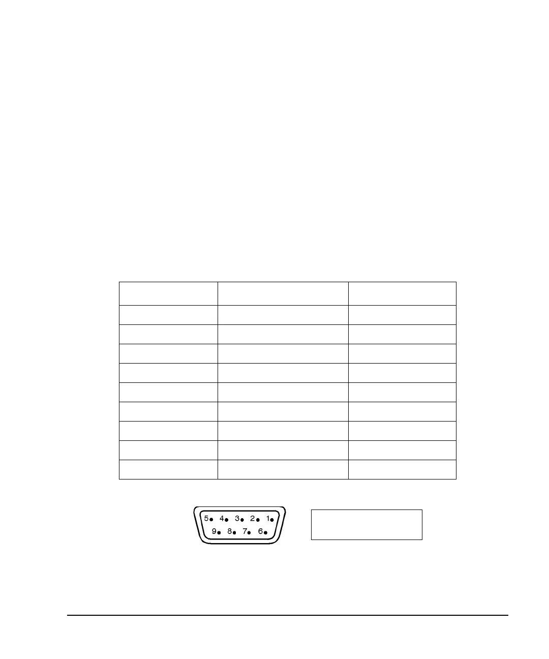
3. RS 232 Connector
This female DB-9 connector is an RS-232 serial port that can be used for controlling the signal generator
remotely. It is functionally equivalent to the GPIB and LAN connectors. The following table shows the
description of the pinouts. Figure 1-5 shows the pin configuration.
Figure 1-5
Table 1-1 RS 232 Connector
Pin Number Signal Description Signal Name
1 No Connection
2 Receive Data RECV
3 Transmit Data XMIT
4+5 V
5 Ground, 0 V
6 No Connection
7Request to SendRTS
8 Clear to Send CTS
9 No Connection
View looking into
rear panel connector

 Loading...


