628 Chapter 17
W-CDMA Downlink Digital Modulation for Receiver Test
Configuring Rear Panel Output Signals
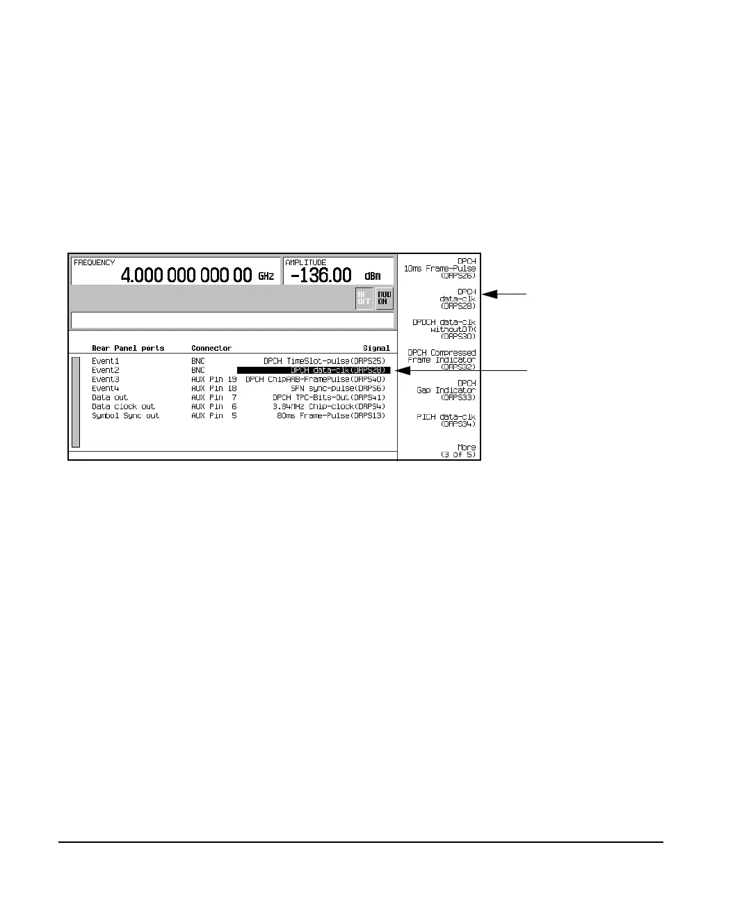
2. Press More (1 of 5) > More (2 of 5) > DPCH data-clk(DRPS28).
Notice that in row two of the table editor under the column Signal, the text
SFN reset-signal(DRPS5) changed to DPCH data-clk(DRPS28). This corresponds to the
Event2 connector listed in the Rear Panel ports column. Figure 17-33 shows what the ESG
display looks like after the DPCH data-clock selection is made.
Figure 17-33 Output Trigger Signal Selection
To exit this display, press either
Mode Setup to return to the first-level W-CDMA softkey menu or press
Return until you come to the desired softkey menu/display.
Deselecting an Output Signal
This procedure builds upon the previous procedure Selecting an Output Signal.
1. Press
More (3 of 5) > More (4 of 5).
2. Highlight the Event2 connector listing.
3. Press
NONE(DRPS0).
Notice that the output signal selection listed in the Signal column has changed to None(RPSO) and is
shown in Figure 17-34. The none indicates that there is no signal output selected for the corresponding
connector.
DPCH data-clock
Selected
DPCH data-clk(DRPS28)
Softkey