460 Chapter 16
W-CDMA Uplink Digital Modulation for Receiver Test
Understanding the PRACH
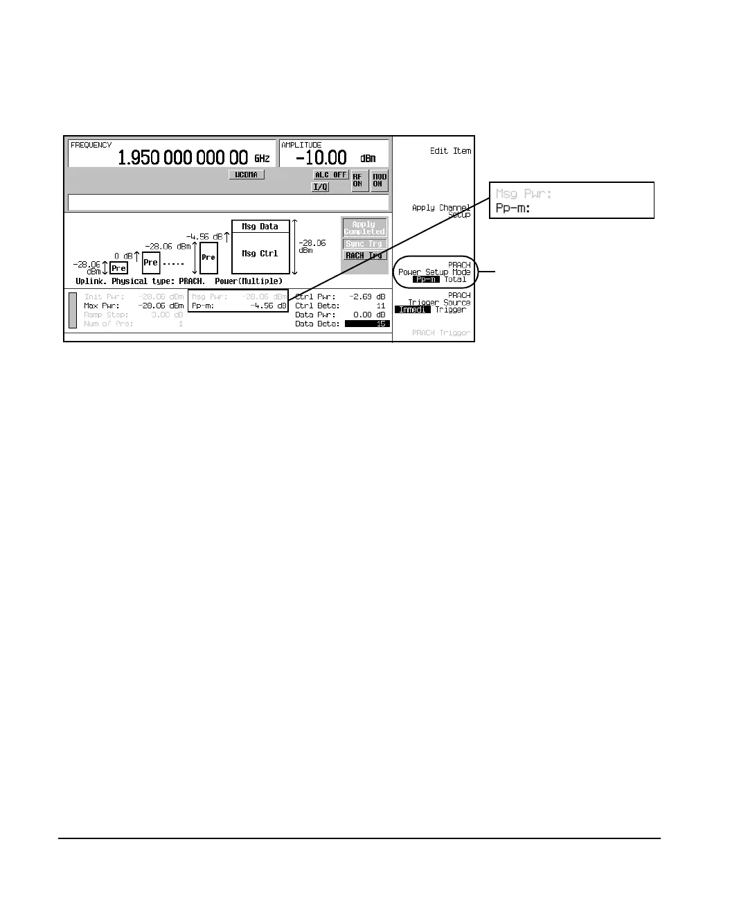
Figure 16-10 Pp-m Mode
Tota l P ower Mode
The total mode lets you set the message part power directly, which in turn sets the control part power by
automatically adjusting the Pp-m value. In this mode, the Msg Pwr field is active and the Pp-m field is
grayed-out (inactive). To calculate what control part power and Pp-m value will result from a message part
power value, perform the following steps where
1. Determine the difference between the relative power values.
Pwr
diff
= Data
pwr − Cntlpwr
2. Calculate the control part power.
Cntl
dBm
= Mess
dBm
− 10 Log[1 + 10
(Pwr diff / 10)
]
3. Calculate the expected Pp-m value.
Pp-m = Cntl
dBm
− Pre
dBm
Pwr
diff
= difference between relative power values Cntl
pwr
= relative control power
Data
pwr
= relative data power Cntl
dBm
= control part power
Pre
dBm
= preamble power Mess
dBm
= message power
Pp-m Power Mode Selected
Pp-m is Active
Msg Pwr is Inactive

 Loading...


