180 Rockwell Automation Publication 750-IN001P-EN-P - April 2017
Chapter 4 Power Wiring
710 kW 9 1175 Light 20G…C1K1 1293 – 1157 1100 1400
(3)
1450 725 2600 1450 725 3500 3500 1450 1352 1600
(3)
1175 Normal 20G…C1K2 1293 1872 1157 1100 1400
(3)
1450 725 2600 1450 725 3500 3500 1450 1352 1600
(3)
1175 Heavy 20G…C1K5 1763 2220 1157 1100 1400
(3)
1450 725 2600 1450 725 3500 3500 1450 1352 1600
(3)
10 1325 Heavy 20G…C1K6 1988 2385 1305 1100 1400
(3)
1650 825 2900 1650 825 3900 3900 1650 1525 1600
(3)
800 kW 9 1465 Light 20G…C1K2 1612 – 1443 1100 1400
(3)
1800 900 3200 1800 900 4300 4300 1800 1686 1600
(3)
1465 Normal 20G…C1K4 1612 2198 1443 1100 1400
(3)
1800 900 3200 1800 900 4300 4300 1800 1686 1600
(3)
850 kW 9 1480 Light 20G…C1K4 1628 – 1457 1100 1400
(3)
1800 900 3300 1800 900 4400 4400 1800 1703 1600
(3)
1480 Normal 20G…C1K5 1628 2220 1457 1100 1400
(3)
1800 900 3300 1800 900 4400 4400 1800 1703 1600
(3)
900 kW 9 1600 Light 20G…C1K5 1760 – 1576 1100 1400
(3)
1950 975 3500 1950 975 4700 4700 1950 1841 1600
(3)
10 1590 Normal 20G…C1K6 1749 2385 1566 1100 1400
(3)
1950 975 3500 1950 975 4700 4700 1950 1830 1600
(3)
1000 kW 10 1715 Light 20G…C1K6 1887 2058 1689 1100 1400
(3)
2100 1050 3800 2100 1050 5100 5100 2100 1974 1600
(3)
1800 Heavy 20G…C2K1 2700 3240 1773 1100 1400
(3)
2200 1100 4000 2200 1100 5300 5300 2200 2071 1600
(3)
1250 kW 10 2150 Normal 20G…C2K1 2365 3240 2117 1100 1400
(3)
2650 1325 4800 2650 1325 6400 6400 2650 2474 1600
(3)
1400 kW 10 2330 Light 20G…C2K1 2563 2796 2294 1100 1400
(3)
2850 1425 5200 2850 1425 6900 6900 2850 2681 1600
(3)
(1) “Applied Rating” refers to the motor that will be connected to the drive. For example, a “C460” drive can be used in Normal Duty mode on a 250 kW motor, in Heavy-duty mode on a 200 kW motor or in Light-duty mode on a 315 kW motor. The drive can be programmed
for each mode. Wiring and fuses can be sized based on the programmed mode. For any given drive catalog number, Normal Duty mode provides higher continuous current but smaller overload current when compared to Heavy-duty mode. See parameter 306 [Duty
Rating]. See Specifications for an explanation of Duty Ratings.
(2) These AC line fuses (with blown fuse indicators) are included in the drive to provide drive short circuit protection. AC input protection devices for branch circuit protection based on US NEC are listed in the table. Each drive bay has one fuse per phase.
(3) Each drive bay has one fuse per DC line.
(4) Minimum protection device size is the lowest rated device that supplies maximum protection without nuisance tripping.
(5) Maximum protection device size is the highest rated device that supplies drive protection. For US NEC, minimum size is 125% of motor FLA. Ratings that are shown are maximum.
(6) Circuit Breaker – inverse time breaker. For US NEC, minimum size is 125% of motor FLA. Ratings that are shown are maximum.
(7) Recommended Motor circuit protector – Instantaneous trip circuit breaker. Set the trip setting to the input current of the drive and size for the continuous current of the system.
(8) These DC line fuses (with blown fuse indicators) are included in the drive to provide drive short circuit protection.
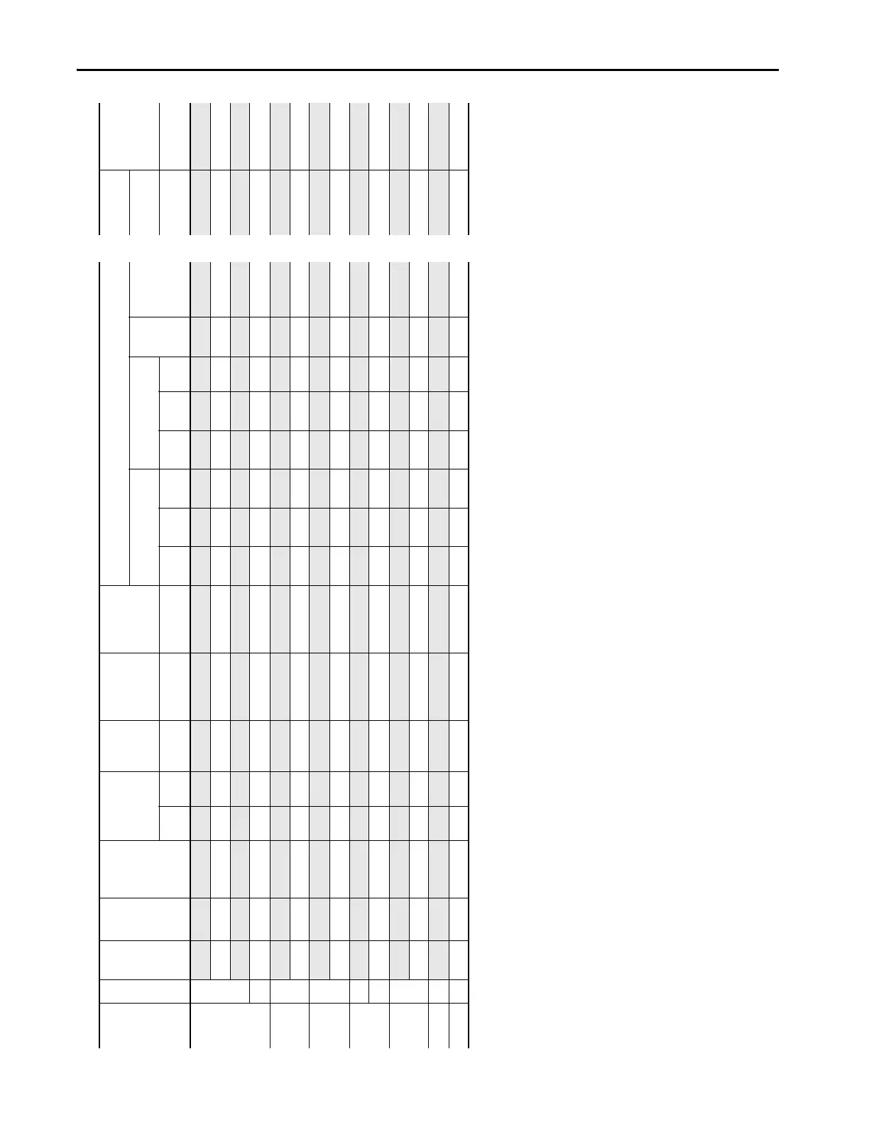
Table 20 - 400 Volt AC and 540 Volt DC Input Protection Devices – Floor Mount Frames 8…10 (Continued)
Applied
Rating
(1)
Frame
Cont.
Output
Amps
Duty Catalog
Number
Output Overload
Amps
Continuous
AC Input
AC Input
Integral
Semiconductor
Fuse Size
(170M)
(2)
DC Bay to Bay
Integral
Semiconductor
Fuse Size
(170M)
AC Input Protection Devices Recommended for Branch Circuit Protection
(Does not apply to 21G Drives with Options)
Input
Quantities
DC Input
Integral
Semiconductor
Fuse Size
(170M)
(8)
Dual Element
Time Delay Fuse
Non-Time Delay Fuse Circuit
Breaker
Max
Size
(6)
Motor
Circuit
Protector
(7)
Continuous DC
Input
1 min 3 sec Amps Amps Amps 1/Phase
Min
(4)
2/Phase
Min
(4)
Max
(5)
1/Phase
Min
(4)
2/Phase
Min
(4)
Max
(5)
Amps Amps
 Loading...

