Rockwell Automation Publication 750-IN001P-EN-P - April 2017 213
Power Wiring Chapter 4
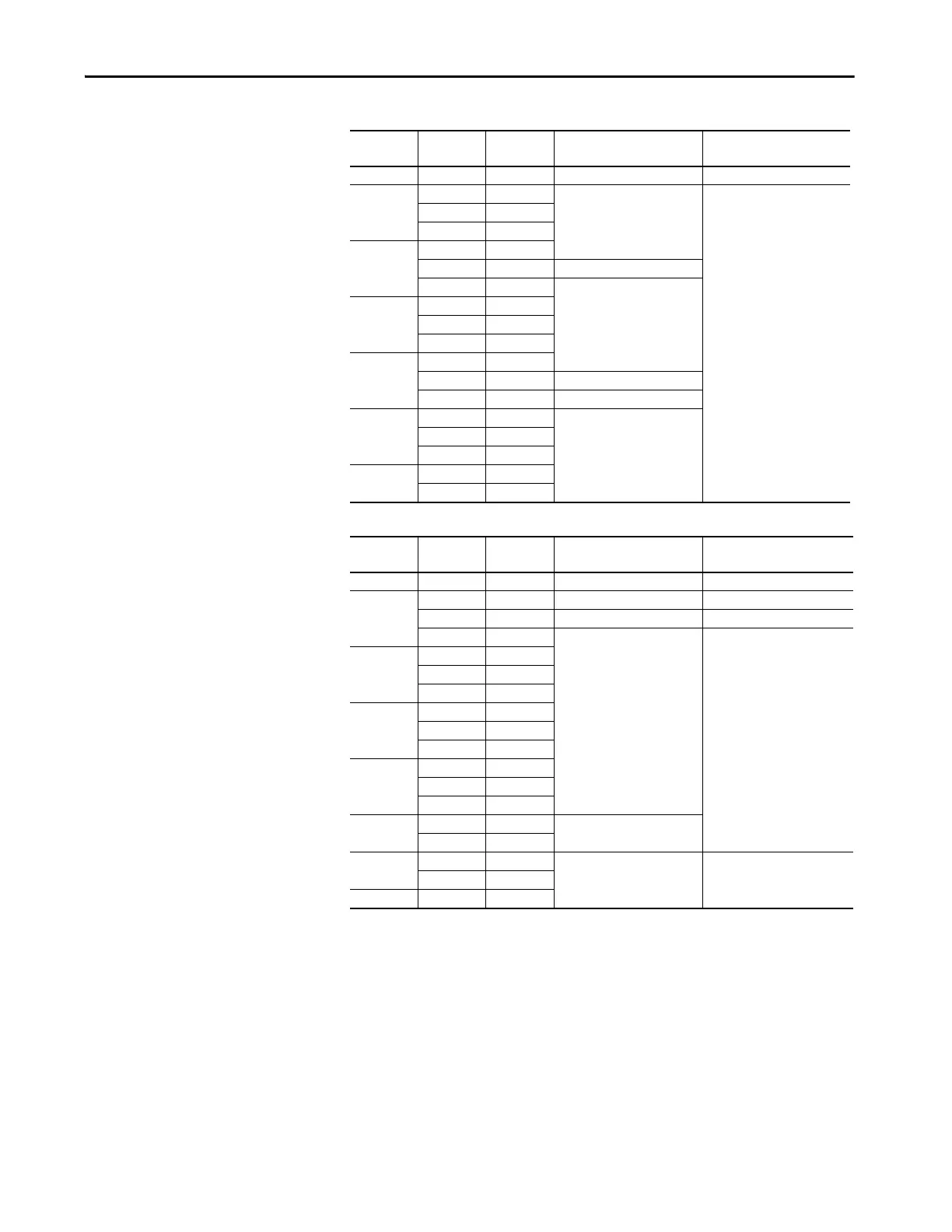
Table 39 - 400V, 50 Hz Input – Code P12 Output Contactor Options (only floor mount Frame 8)
Table 40 - 480V, 60 Hz Input – Code P12 Output Contactor Options (only floor mount Frame 8)
kW Amps Duty Contactor Cat. No. Recommended Torque
N•m (lb•in)
200 385 Heavy 100-D420EA11 17 (150)
250
460 Normal
100-D630EA11
68 (600)
456 Heavy
472 Heavy
315
540 Light
540 Normal 100-D860EA11
540 Heavy
100-D630EA11315
585 Light
567 Normal
585 Heavy
355
612 Light
650 Normal 100-D860EA11
642 Heavy 100-D630EA11
400
750 Light
100-D860EA11
750 Normal
770 Normal
450
796 Light
832 Light
kW Amps Duty Contactor Cat. No. Recommended Torque
N•m (lb•in)
300 370 Heavy 100-D420ED11 17 (150)
350
430 Normal 100-D630ED11 68 (600)
414 Heavy 100-D420ED11 17 (150)
454 Heavy
100-D630ED11
68 (600)
400
485 Light
485 Normal
485 Heavy
450
545 Light
545 Normal
545 Heavy
500
590 Light
617 Normal
617 Heavy
600
710 Light
100-D860ED11
710 Normal
650
765 Light
100-G1200KD12 60 (528)740 Normal
700 800 Light
 Loading...

