214 Rockwell Automation Publication 750-IN001P-EN-P - April 2017
Chapter 4 Power Wiring
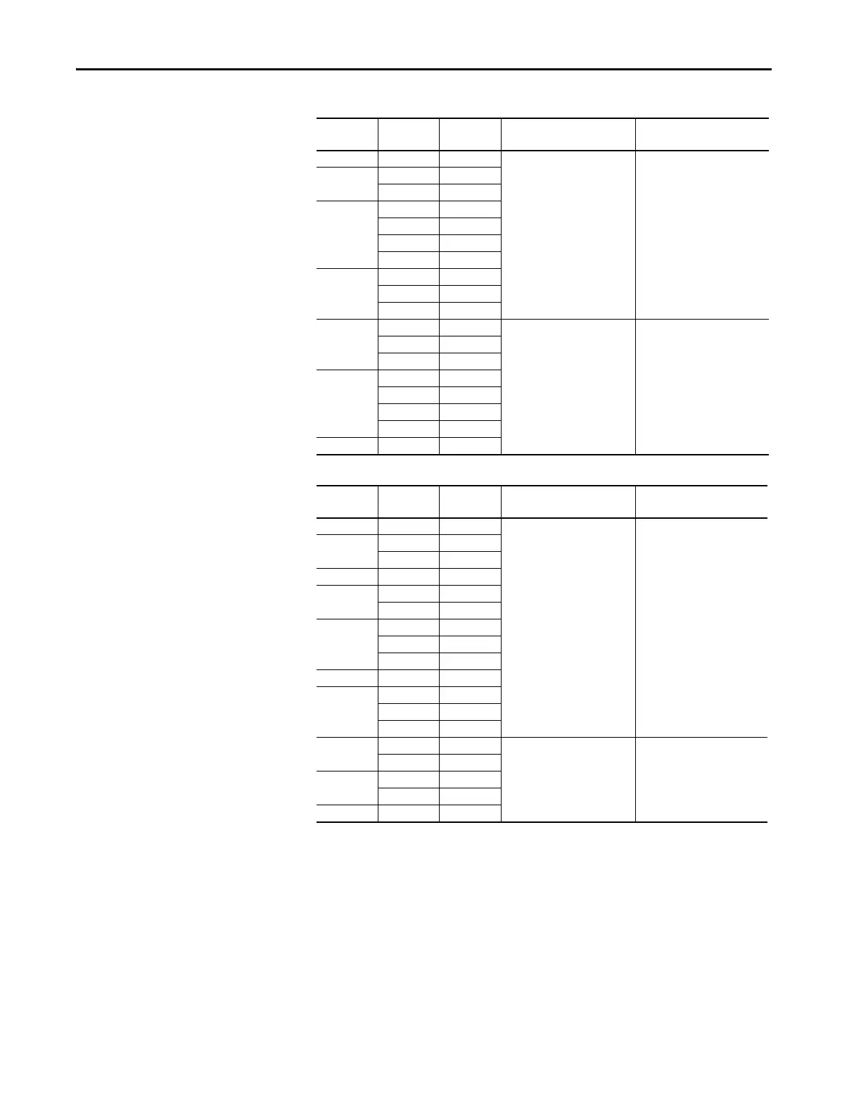
Table 41 - 600V, 50 Hz Input – Code P12 Output Contactor Options (only floor mount Frame 8)
Table 42 - 690V, 60 Hz Input – Code P12 Output Contactor Options (only floor mount Frame 8)
Hp Amps Duty Contactor Cat. No. Recommended Torque
N•m (lb•in)
250 272 Heavy
100-D420ED11 17 (150)
300
295 Heavy
295 Normal
350
329 Heavy
355 Heavy
355 Light
355 Normal
400
395 Heavy
395 Light
395 Normal
450
425 Heavy
100-D630ED11 68 (600)
435 Light
435 Normal
500
460 Light
460 Normal
510 Light
510 Normal
550 545 Light
kW Amps Duty Contactor Cat. No. Recommended Torque
N•m (lb•in)
200 215 Heavy
100-D420EA11 17 (150)
250
265 Heavy
265 Normal
300 308 Heavy
315
330 Light
330 Normal
355
370 Heavy
370 Light
370 Normal
375 375 Heavy
400
410 Light
413 Heavy
415 Normal
450
460 Light
100-D630EA11 68 (600)
460 Normal
500
500 Light
500 Normal
530 530 Light
 Loading...

