Rockwell Automation Publication 1756-UM001M-EN-P - February 2012 197
SIL 2 Certification Chapter 13
Figure 44 on page 196 shows a typical SIL loop that uses redundancy,
including the following:
• The overall safety loop
• The ControlLogix portion of the overall safety loop
• How other devices (for example, HMI) connect to the loop, while
operating outside the loop
Fault-tolerant Configuration
The most recently-certified ControlLogix SIL2 configuration is the fault-
tolerant configuration. The fault-tolerant configuration of the ControlLogix
system uses fully-redundant controllers, communication modules, and remote
I/O.
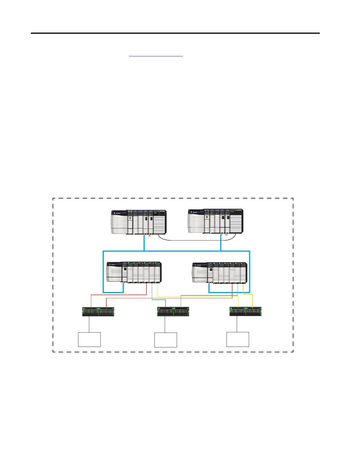
Figure 45 - Fault-tolerant Configuration
The fault-tolerant configuration uses safety and programming principles
described in this manual, as well as programming and hardware described in
the application technique manuals.
PRI COM OK
PRI COM OK
ST
ST
DIAGNOSTIC
O
K
0 1 234 567
8910111213 1415
DC INTPUT
ST
ST
DIAGNOSTIC
O
K
0 1 234 567
8910111213 1415
DC INTPUT
ANALOG INTPUT
CAL
OK
ANALOG INTPUT
CAL
OK
ST
ST
DIAGNOSTIC
O
K
0 1 234 567
8910111213 1415
DC OUTPUT
ST
ST
DIAGNOSTIC
O
K
0 1 234 567
8910111213 1415
DC OUTPUT
ST
ST
DIAGNOSTIC
O
K
0 1 234 567
8910111213 1415
DC INTPUT
ST
ST
DIAGNOSTIC
O
K
0 1 234 567
8910111213 1415
DC INTPUT
ANALOG INTPUT
CAL
OK
ANALOG INTPUT
CAL
OK
ST
ST
DIAGNOSTIC
O
K
0 1 234 567
8910111213 1415
DC OUTPUT
ST
ST
DIAGNOSTIC
O
K
0 1 234 567
8910111213 1415
DC OUTPUT
Field Device
Field Device
Field Device
Primary Chassis
Digital Input
Termin atio n
Board
Digital Output
Termination Board
SIL2-certified ControlLogix Safety Loop
Analog Input
Termination
Board
Secondary Chassis
I/O Chassis A
I/O Chassis B
 Loading...

