Publication 1766-RM001A-EN-P - October 2008
Using the High-Speed Counter and Programmable Limit Switch 131
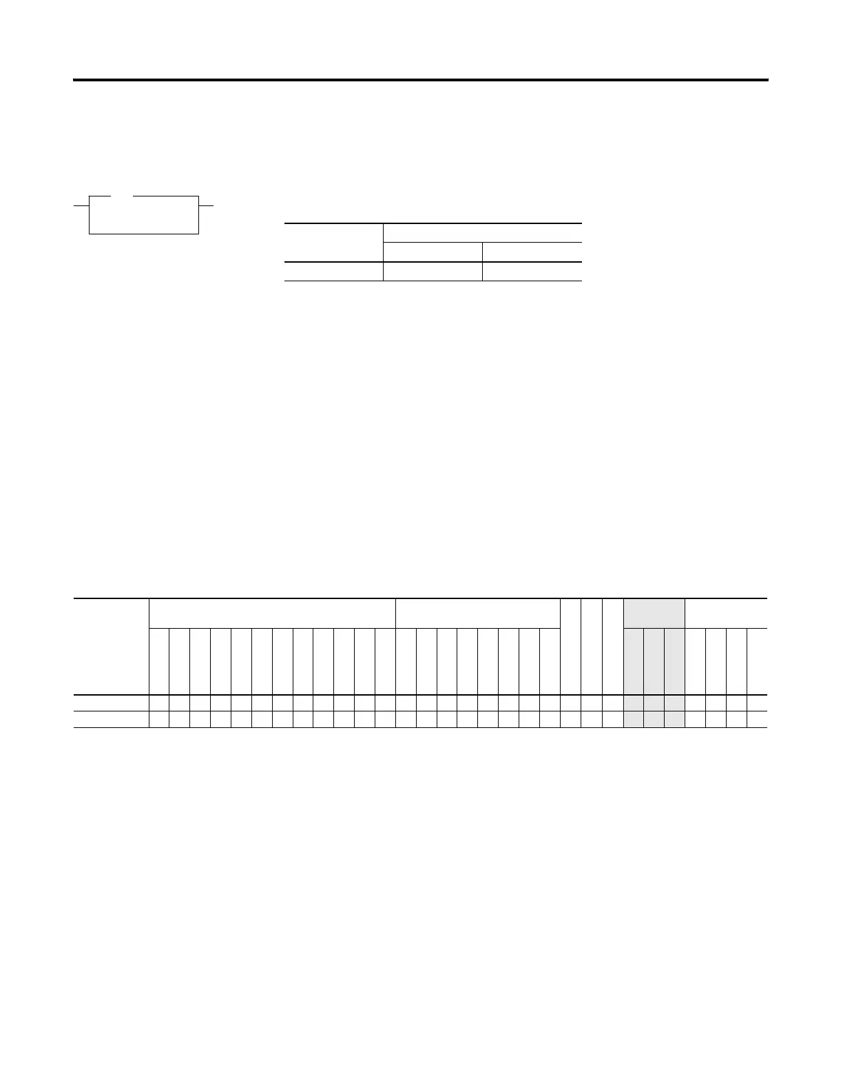
RAC - Reset
Accumulated Value
Instruction Type: output
The RAC instruction resets the high-speed counter and allows a specific
value to be written to the HSC accumulator. The RAC instruction uses the
following parameters:
• Counter Number - Specifies which high-speed counter is being
used:
– Counter Number 0 = HSC0, 1 = HSC1, 2 = HSC2, 3 = HSC3, 4 =
HSC4, 5 = HSC5
• Source - Specifies the location of the data to be loaded into the HSC
accumulator. The data range is from -2,147,483,648…2,147,483,647.
Valid Addressing Modes and File Types are shown below:
RAC
Reset Accumulated Value
Counter HSC0
Source 0
RAC
Controller Execution Time When Rung Is:
True False
MicroLogix 1400 8.3310 µs 0.2030 µs
RAC Instruction Valid Addressing Modes and File Types
For definitions of the terms used in this table see Using the Instruction Descriptions on page 92.
Parameter
Data Files Function Files
CSF - Comms
IOS - I/O
DLS - Data Log
Address
Mode
Address Level
O
I
S
B
T, C, R
N
F
ST
L
MG, PD
RI/RIX
PLS
RTC
HSC
PTOX, PWMX
STI
EII
BHI
MMI
LCD
Immediate
Direct
Indirect
Bit
Word
Long Word
Element
Counter Number •
Source • • • ••
efesotomasyon.com - Allen Bradley,Rockwell,plc,servo,drive

 Loading...


