Publication 1766-RM001A-EN-P - October 2008
Communications Instructions 399
The Message Element
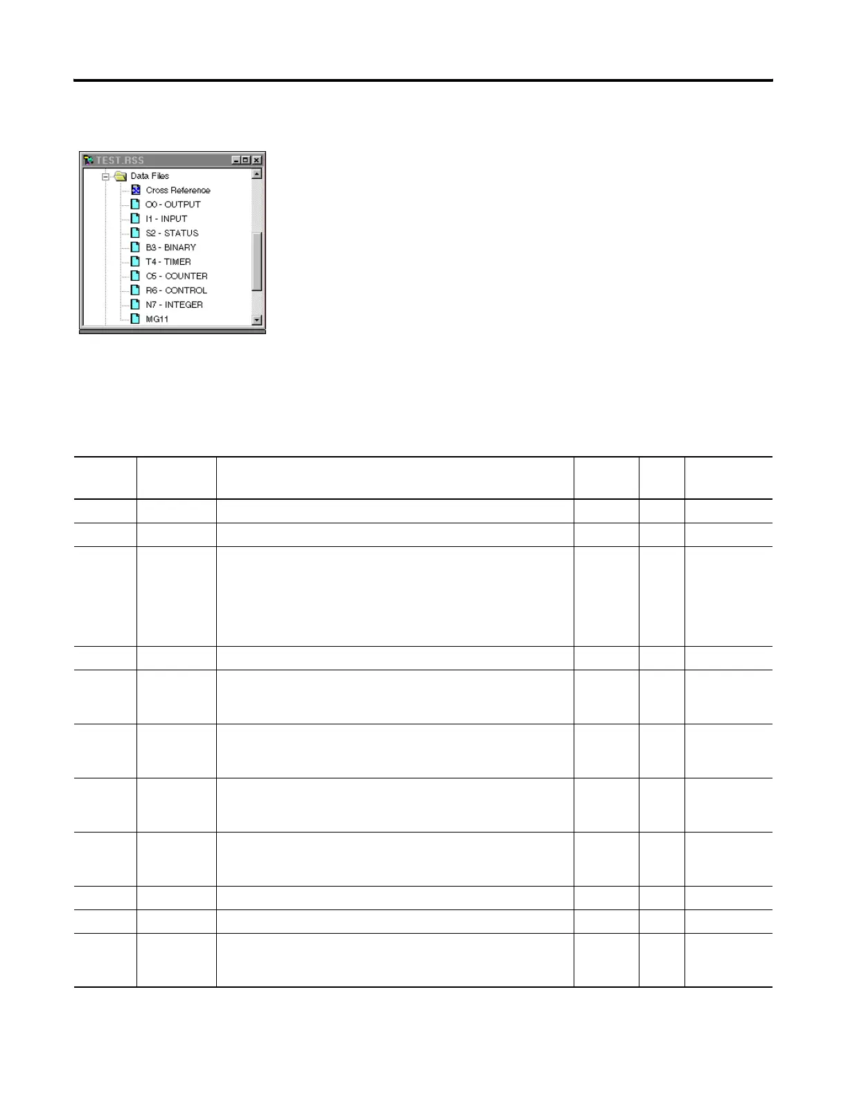
The MSG instruction built into the controller uses a MG data file to
process the message instruction. The MG data file, shown at left, is
accessed using the MG prefix. Each message instruction utilizes an
element within a MG data file. For example, MG11:0 is the first element in
message data file 11.
Message File Sub-Elements
Each MSG instruction must use a unique Element in a MSG File. The MSG
element for each MSG instruction holds all of the parameters and status
information for that particular MSG instruction.
Each MSG File Element consists of Sub-Elements 0…24 as shown in the
following table.
Message File Elements
Sub-
Element
Name Description Paramet
er
Size User Program
Access
(2)
0 to 1 Reserved Word read only
2 Messaging Type: 0 (for PCCC), 1 (for CIP), 2 (for Modbus Master) Word read only
3 for PCCC Messaging: bits 07-00 (CMD code), bits 15-08 (FNC code)
for CIP: bits 07-00 (Service Code), bits 15-08 (Supplemental Object
Path Data Count)
for Modbus Master: bits 07-00 (Function Code), bits 15-08 (Reserved)
derived Word read only
4 Internal Physical Address Word read only
5 MG11:0.RBL PCCC: Remote Bridge Link ID
Modbus Master: not used
Y Word read only
6 MG11:0.LBN PCCC: Local Bridge Node Address
Modbus Master: not used
Y Word read only
7 MG11:0.RBN PCCC: Remote Bridge Node Address
Modbus Master: not used
Y Word read only
8 MG11:0.CHN Channel: bits 07-00 (0 for Channel 0,1 for Channel 1)
Slot: bits 15-08 (Not used)
Y Word read/write
9 MG11:0.NOD Target Node Number Y Word read/write
10 MG11:0.MTO Message timeout setting or preset in seconds Y Word read/write
11 PCCC: Number of bytes to read/write
Modbus Master: Number of Modbus elements to read/write
Word read only
efesotomasyon.com - Allen Bradley,Rockwell,plc,servo,drive

 Loading...


