Publication 1766-RM001A-EN-P - October 2008
I/O Configuration 35
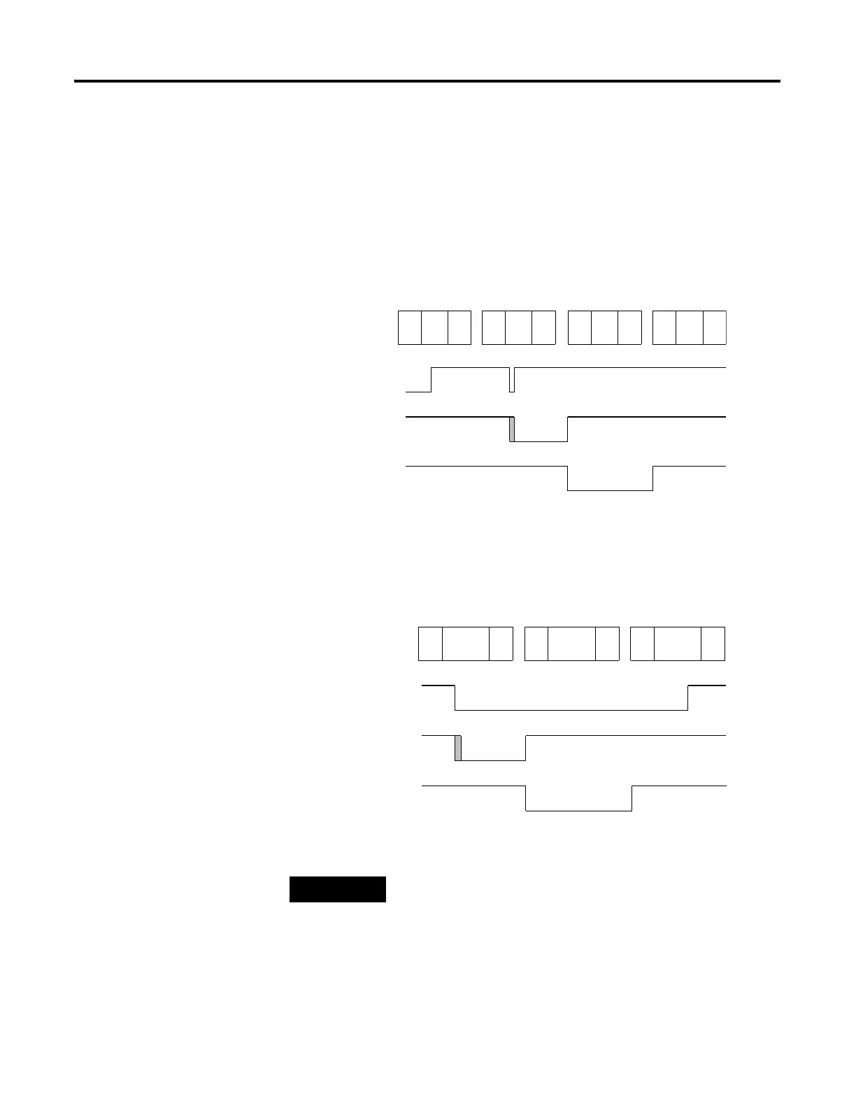
• The detection is on the “falling edge” of the external input.
• The input image is normally “on” (1), and changes to “off” (0) for
one scan.
Falling Edge Behavior - Example 1
Falling Edge Behavior - Example 2
TIP
The “gray” area of the Latched Status waveform is the input filter delay.
Scan Number (X) Scan Number (X+1) Scan Number (X+2)
External
Input
Latched
Status
Input File
Value
Input
Scan
Ladder
Scan
Output
Scan
Scan Number (X+3)
Input
Scan
Ladder
Scan
Output
Scan
Input
Scan
Ladder
Scan
Output
Scan
Input
Scan
Ladder
Scan
Output
Scan
Scan Number (X) Scan Number (X+1) Scan Number (X+2)
External
Input
Latched
Status
Input File
Value
Input
Scan
Ladder
Scan
Output
Scan
Input
Scan
Ladder
Scan
Output
Scan
Input
Scan
Ladder
Scan
Output
Scan
efesotomasyon.com - Allen Bradley,Rockwell,plc,servo,drive

 Loading...


