26 Rockwell Automation Publication 20A-UM001N-EN-P - July 2013
Chapter 1 Programming and Parameters
MOTOR CONTROL (file B)
Torq Attributes
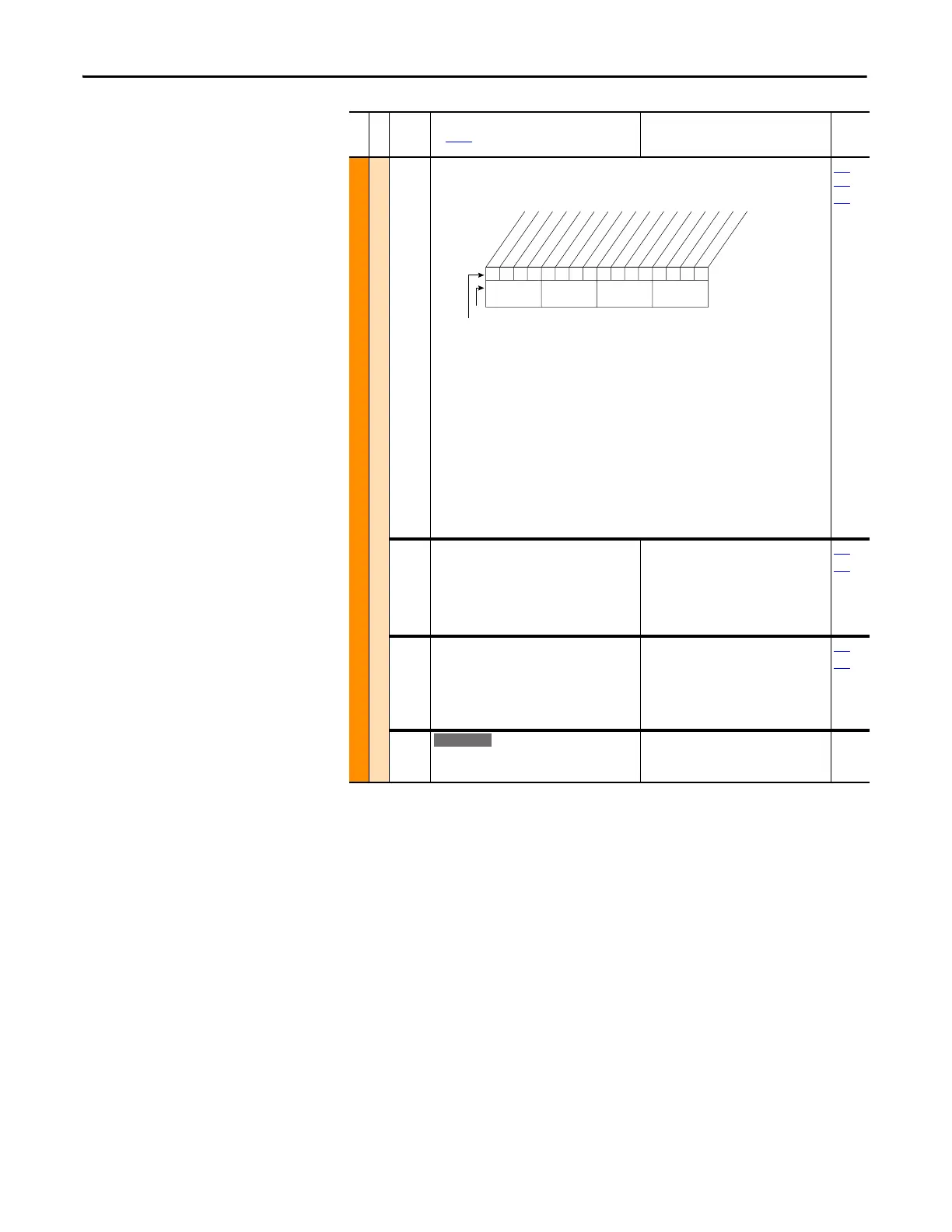
056 [Compensation]
Enables/disables correction options.
Option Descriptions:
• Reflect Wave – Provides reflected wave overvoltage protection for long cable lengths.
(typically enabled).
• Enable Jerk – In non-FVC Vector modes, disabling jerk removes a short S-curve at the start
of the accel/decel ramp.
• Ixo AutoCalc – Not functional – reserved for future enhancements.
• Xsistor Diag – Power transistor power diagnostic tests run at each start command.
• Rs Adapt – only FVC w/Encoder – Disabling can improve torque regulation at lower
speeds (typically not needed).
• PWM Freq Lock – Keeps the PWM frequency from decreasing to 2 kHz at low operating
frequencies in FVC Vector mode without encoder.
• DigIn DatLog – Enables logic functions that can be applied to parameter 411 [DigIn
DataLogic] and the specified digital input.
140
…
143
411
057 [Flux Up Mode]
Auto = Flux is established for a calculated time
period based on motor nameplate data. [Flux
Up Time] is not used.
Manual = Flux is established for [Flux Up Time]
before acceleration.
Default:
Options:
0
0
1
“Manual”
“Manual”
“Automatic”
053
058
058 [Flux Up Time]
Sets the amount of time the drive uses to try
and achieve full motor stator flux. When a Start
command is issued, DC current at current limit
level is used to build stator flux before
accelerating.
Default:
Min/Max:
Units:
0.00 Secs
0.00/5.00 Secs
0.01 Secs
053
058
059 [SV Boost Filter]
Sets the amount of filtering used to boost
voltage during Sensorless Vector operation.
Default:
Min/Max:
Units:
500
0/32767
1
File B
Group
No.
Parameter Name and Description
See page 14 for symbol descriptions
Values
Related
10111xx1x0xxxxxx
10 01234567891112131415
1=Enabled
0=Disabled
x =Reserved
Bit #
Factory Default Bit Values
Reflect Wave
Enable Jerk
Ixo AutoCalc
Xsistor Diag
(1)
Rs Adapt
(2)
PWM Freq Lock
(2)
DigIn DatLog
(2)
Nibble 1Nibble 2Nibble 3Nibble 4
(1)
Enhanced firmware 1.001 & later.
(2)
Enhanced firmware 2.001 & later.
E C

 Loading...


