40 Rockwell Automation Publication 20A-UM001N-EN-P - July 2013
Chapter 1 Programming and Parameters
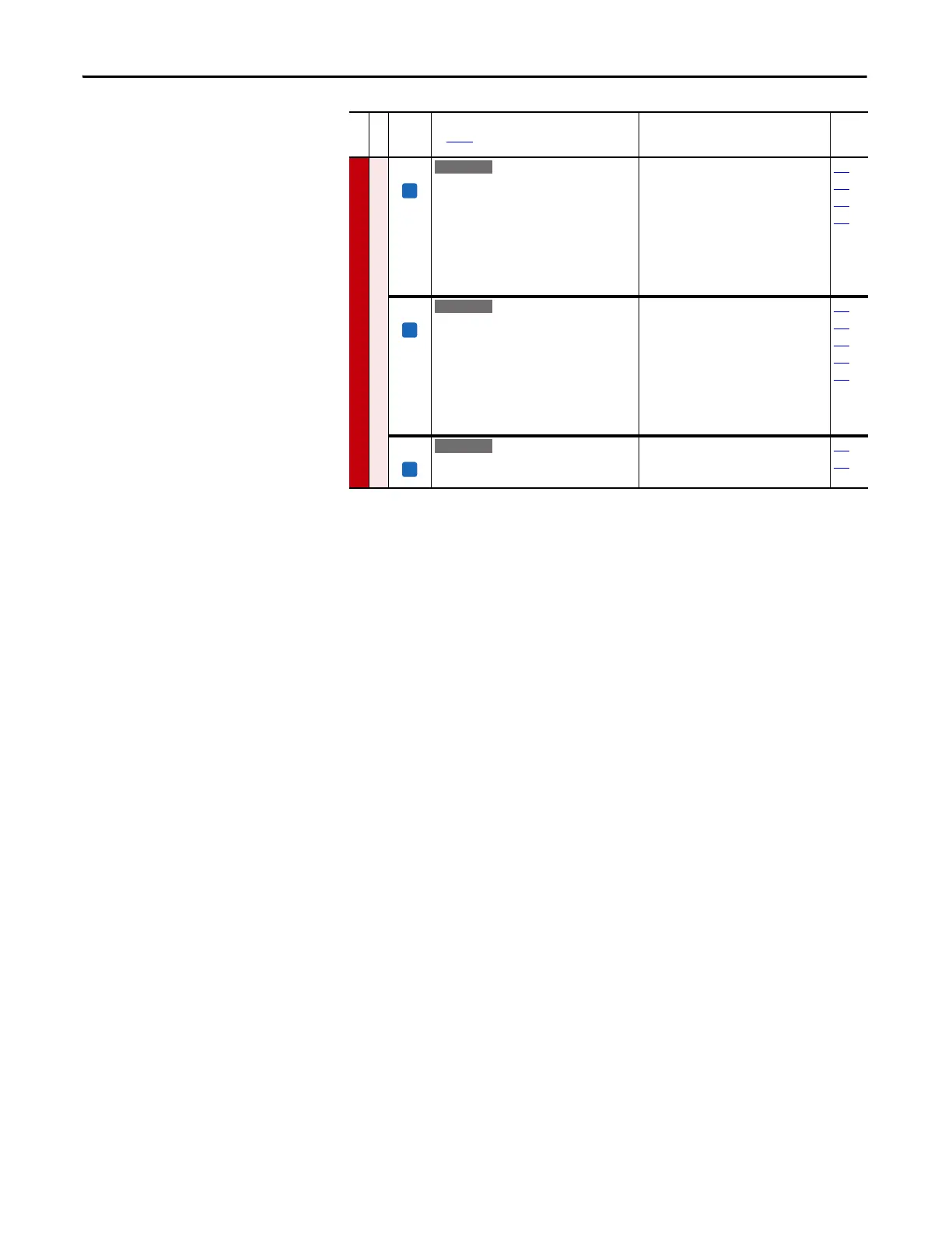
SPEED COMMAND (file C)
Speed Regulator
449 [Speed Desired BW]
Sets the speed loop bandwidth and determines
the dynamic behavior of the speed loop. As
bandwidth increases, the speed loop becomes
more responsive and can track a faster
changing speed reference.
Adjusting this parameter causes the drive to
calculate and change P445 [Ki Speed Loop] and
P446 [Kp Speed Loop] gains.
Default:
Min/Max:
Units:
0.0 Radians/Sec
0.0/250.0 Radians/Sec
0.1 Radians/Sec
053
067
445
446
450 [Total Inertia]
Represents the time in seconds, for a motor
coupled to a load to accelerate from zero to
base speed, at rated motor torque. The drive
calculates Total Inertia during the autotune
inertia procedure.
Adjusting this parameter causes the drive to
calculate and change P445 [Ki Speed Loop] and
P446 [Kp Speed Loop] gains.
Default:
Min/Max:
Units:
0.10 Secs
0.01/600.0 Secs
0.01 Secs
053
067
445
446
449
451 [Speed Loop Meter]
Value of the speed regulator output. When in
FVC mode, units are in percent.
Default:
Min/Max:
Units:
Read Only
±800.0%/Hz
0.1%/Hz
053
121
File C
Group
No.
Parameter Name and Description
See page 14 for symbol descriptions
Values
Related
E C v2

 Loading...


