Rockwell Automation Publication 750-IN100B-EN-P - July 2017 137
I/O Wiring Chapter 6
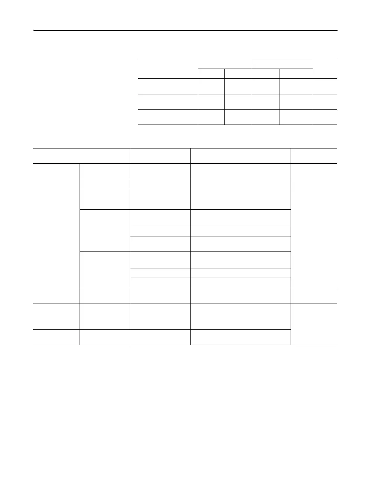
Table 18 - Common DC Input Drive Assembly I/O Terminal Block and Connector Specifications
Name Wire Size Range Torque Strip
Length
Maximum Minimum Maximum Recommended
Common DC Input TB1…TB5 4.0 mm
2
(12 AWG)
0.25 mm
2
(24 AWG)
0.5 N•m
(4.4 lb•in)
0.4 N•m
(3.5 lb•in)
7 mm
(0.28 in.)
Fiber Interface PCB Connector
P13
4.0 mm
2
(12 AWG)
0.25 mm
2
(24 AWG)
0.5 N•m
(4.4 lb•in)
0.4 N•m
(3.5 lb•in)
7 mm
(0.28 in.)
Fiber Interface PCB Connector
P14
2.5 mm
2
(14 AWG)
0.3 mm
2
(28 AWG)
0.25 N•m
(2.2 lb•in)
0.2 N•m
(1.8 lb•in)
6 mm
(0.24 in.)
Table 19 - I/O Wire Recommendations
Type Wire Type(s) Description Min. Insulation
Rating
Signal
(1)(2)(3)
Standard Analog I/O – 0.750 mm
2
(18AWG), twisted pair, 100% shield with
drain.
300V,
75…90 °C
(167…194 °F)
Remote Pot – 0.750 mm
2
(18AWG), 3 conductor, shielded.
Encoder/
Pulse I/O
<30 m (100 ft)
Combined 0.196 mm
2
(24AWG)
individually shielded pairs.
Encoder/
Pulse I/O
30…152 m
(100…500 ft)
Signal 0.196 mm
2
(24AWG)
individually shielded pairs.
Power 0.750 mm
2
(18AWG) in.dividually shielded pairs
Combined 0.330 mm
2
(22AWG), power is 0.500 mm
2
(20AWG)
individually shielded pairs.
Encoder/
Pulse I/O
152…259 m
(500…850 ft.)
Signal 0.196 mm
2
(24AWG)
individually shielded pairs.
Power 0.750 mm
2
(18AWG) individually shielded pairs.
Combined 0.750 mm
2
(18AWG) individually shielded pairs.
Control Power Un-shielded – Per US NEC or applicable national or local code. 300V,
60 °C (140 °F)
Digital I/O
Safety Inputs
Homing Inputs
(1)(2)(3)(4)
Shielded Multi-conductor shielded cable 0.750 mm
2
(18AWG), 3 conductor, shielded. 300V,
60 °C
(140 °F)
Digital I/O
Homing Inputs
(1)(2)(3)
Un-shielded – Per US NEC or applicable national or local code.
(1) Signal wires should be separated from power wires by at least 0.3 meters (1 foot).
(2) If the wires are short and contained within a enclosure which has no sensitive circuits, the use of shielded wire may not be necessary, but is always recommended.
(3) I/O terminals labeled ‘(–)’ or ‘Common’ are not referenced to earth ground and are designed to greatly reduce common mode interference. Grounding these terminals can cause signal noise.
(4) Safety option modules 20-750-S, 20-750-S1, and 20-750-S3 require shielded cable.

 Loading...


