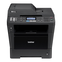
Do you have a question about the Brother DCP-8157DN and is the answer not in the manual?
| Print Technology | Laser |
|---|---|
| Max Resolution (B&W) | 1200 x 1200 dpi |
| Duplex Printing | Yes |
| Scan Resolution | 1200 x 1200 dpi |
| Network Ready | Yes |
| Functions | Copier, Printer, Scanner |
| Scanner Type | Flatbed, ADF |
| Interface | USB, Ethernet |
| Print Resolution | 1200 x 1200 dpi |
| Connectivity | USB, Ethernet |
| Operating Systems Compatibility | Windows, Mac, Linux |
Provides a comprehensive overview of the technical specifications for all supported models.
Details core technical parameters such as print method, resolution, speed, and power consumption.
Outlines wired and wireless network capabilities, node types, and security protocols supported by models.
Lists machine life, part life, MTBF, MTTR, and periodical maintenance part lifespans.
Details toner cartridge yields, drum unit life, and shelf life under various conditions.
Covers paper input/output capacities, supported paper types, weights, and sizes for all trays.
Provides optical and interpolated resolution, and scanning speed for monochrome and color.
Essential safety guidelines to prevent secondary problems during maintenance and troubleshooting.
Lists critical checks for operating environment, power supply, paper, and consumables before repairs.
Illustrates internal printer and ADF/scanner unit components with labels for identification.
Explains the specific function and operation of each mechanical and electrical part.
Lists all error codes, their problems, and cross-references to specific troubleshooting sections.
Provides detailed steps for diagnosing and resolving common problems and error causes.
Crucial safety warnings and precautions for handling parts and preventing damage during disassembly.
Visual guide to all screws used in the machine, aiding part identification.
Specifies the correct torque for tightening screws during reassembly for proper component seating.
Illustrates the correct paths for routing various harnesses during reassembly for proper connectivity.
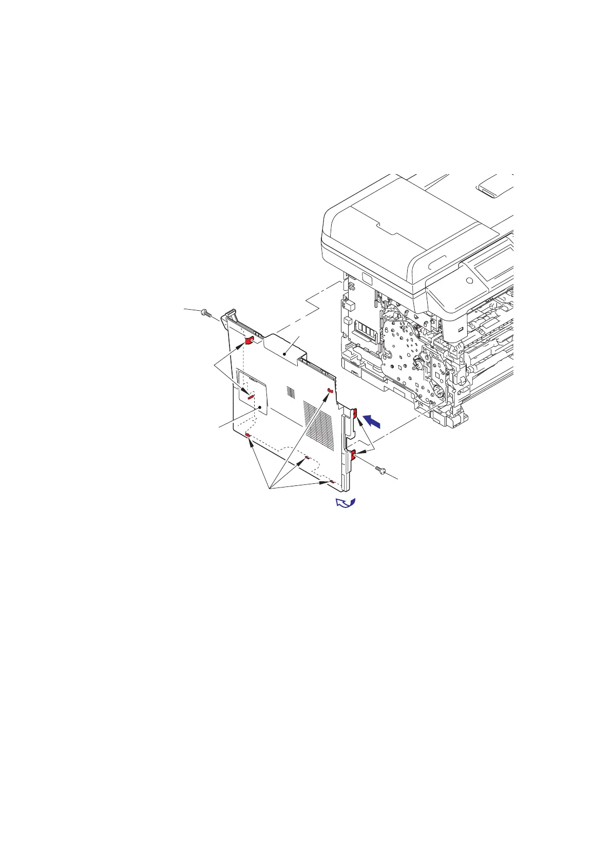
Detailed procedures for disassembling major machine components and sub-assemblies.
Covers firmware installation, country setting, EEPROM initialization, and serial number setup after PCB replacement.
Details the process for entering the laser unit's adjusted values and serial number for proper operation.
Outlines the steps for entering adjusted values after replacing the laser unit.
Describes acquiring white level data after replacing scanner, ADF, or CIS components.
Explains how to enter and use maintenance mode for various diagnostic and setting functions.
Provides a reference table of all available maintenance mode functions with corresponding codes and page numbers.
Explains the purpose and operation procedures for specific maintenance mode functions.
Details how to reset counters for parts like drum, fuser, and paper feed kits after replacement.
Presents the overall wiring diagram showing PCB connections and component interrelations.
Crucial safety warnings and precautions specific to performing periodical maintenance.
Lists parts that require periodic replacement, such as fuser, laser, and paper feeding kits.
Step-by-step instructions for disassembling and removing the fuser unit.
Step-by-step instructions for disassembling and removing the laser unit.