3-90
Confidential
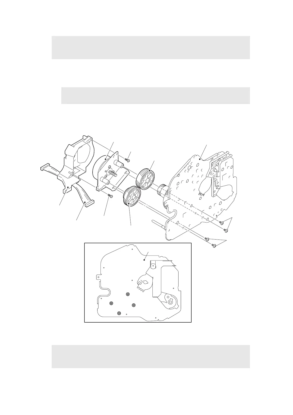
(2) Remove the four taptite cup S M3x8 SR screws, and remove the main motor ASSY and
the main motor cover from the drive sub ASSY.
(3) Remove the fuser gear 35/83R and the DRM gear 32/83R from the main motor ASSY.
(4) Disconnect the main motor harness from the main motor ASSY.
(5) Remove the two taptite bind B M3x10 screws, and remove the main motor ASSY from
the main motor cover.
Fig. 3-119
Note:
• Do not allow the metallic gear shaft of the main motor ASSY and drive sub ASSY to
face down. Failure to observe this may cause the steel plate to be bend.
Note:
• Be careful not to damage the gear teeth.
Assembling Note:
• When securing the main motor cover with screws, tighten the screws in the sequence
of the alphabetical characters engraved on the drive sub ASSY.
Drive sub ASSY
Main motor harness
DRM gear 32/83R
Taptite bind B M3x10
Main motor ASSY
Main motor cover
Taptite bind B M3x10
Fuser gear 35/83R
Taptite cup S
M3x8 SR
Taptite cup S
M3x8 SR
Drive sub ASSY
a
b
d
c
 Loading...