15
Input/Output (SIOB) Boards
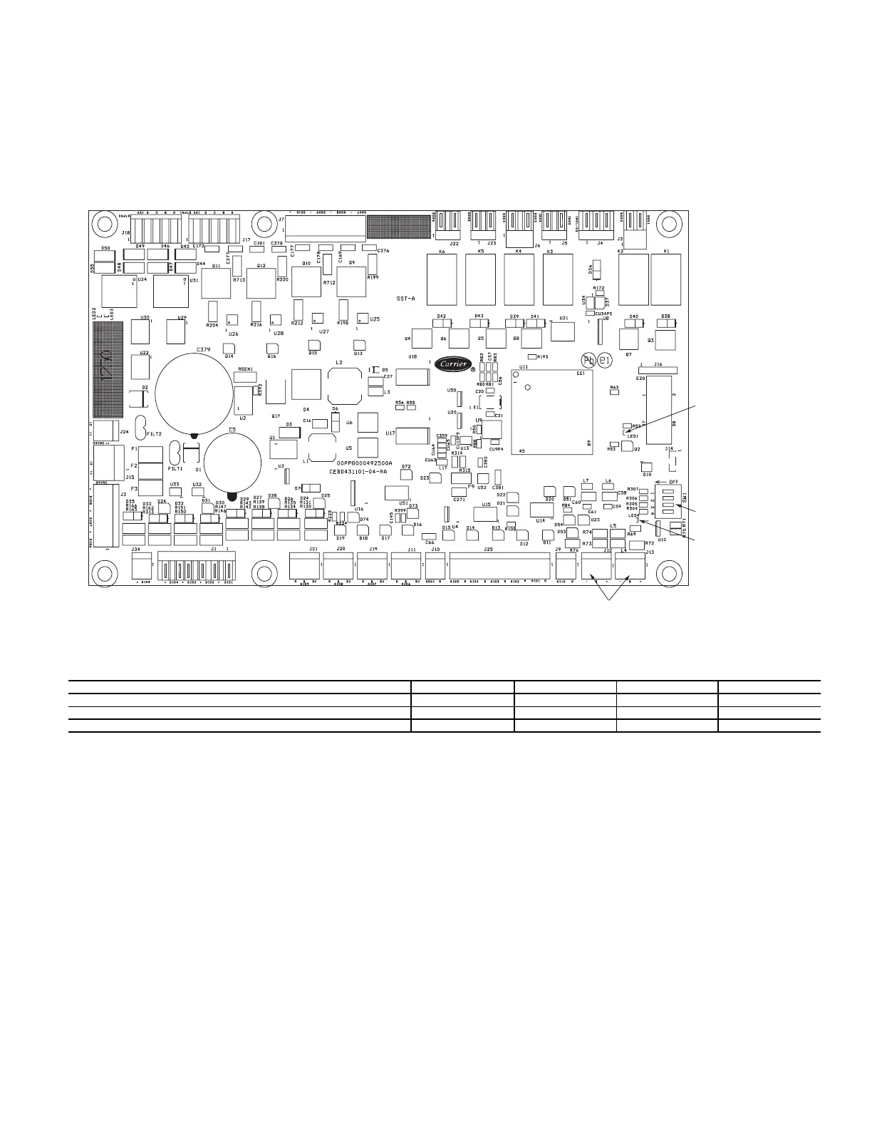
There are two SIOBs for each unit, SIOB-A (address 49) for Cir-
cuit A and SIOB-B (address 50) for Circuit B. See Fig. 19. These
boards receive inputs from thermistors, transducers, demand limit
switch, dual set point switch, remote on/off switch, chilled water
flow switch, oil level switch, pump interlock contact, compressor
VFD enable contact, and evaporator heater current sensing switch,
and provide output control to expansion valves, oil and variable
load matching solenoids, evaporator heater contactor, isolation
valves, oil heater relays, customer supplied pump relays, compres-
sor VFD enable relays, and customer-supplied alarm and running
relays. Information is transmitted between the SIOBs and the
Carrier Controller module via a 3-wire communication bus or
LEN bus. Connections for the LEN bus are J12 and J13. Each
SIOB has a 4-position DIP switch bank used for addressing of the
board. SIOB-A is at address 49 and SIOB-B is at address 50. See
Table 6 for SIOB DIP switch settings. See Tables 7 and 8 for a list
of inputs and outputs for the two SIOBs.
Fig. 19 — SIOB
Table 6 — SIOB A and B DIP Switch Settings
SIOB-A DIP Switch 1 2 3 4
Position OFF OFF OFF OFF
SIOB-B DIP Switch 1 2 3 4
Position ON OFF OFF OFF
a30-5864
DIP
SWITCH
GREEN LED - LEN
(Local Equipment Network)
RED LED - STAT US
LEN CONNECTION
 Loading...


