57
and the unit will operate to that value. This mode will termi-
nate when the Ice Cooling Ice Set-point is no longer in use
(ICE DONE switch is closed).
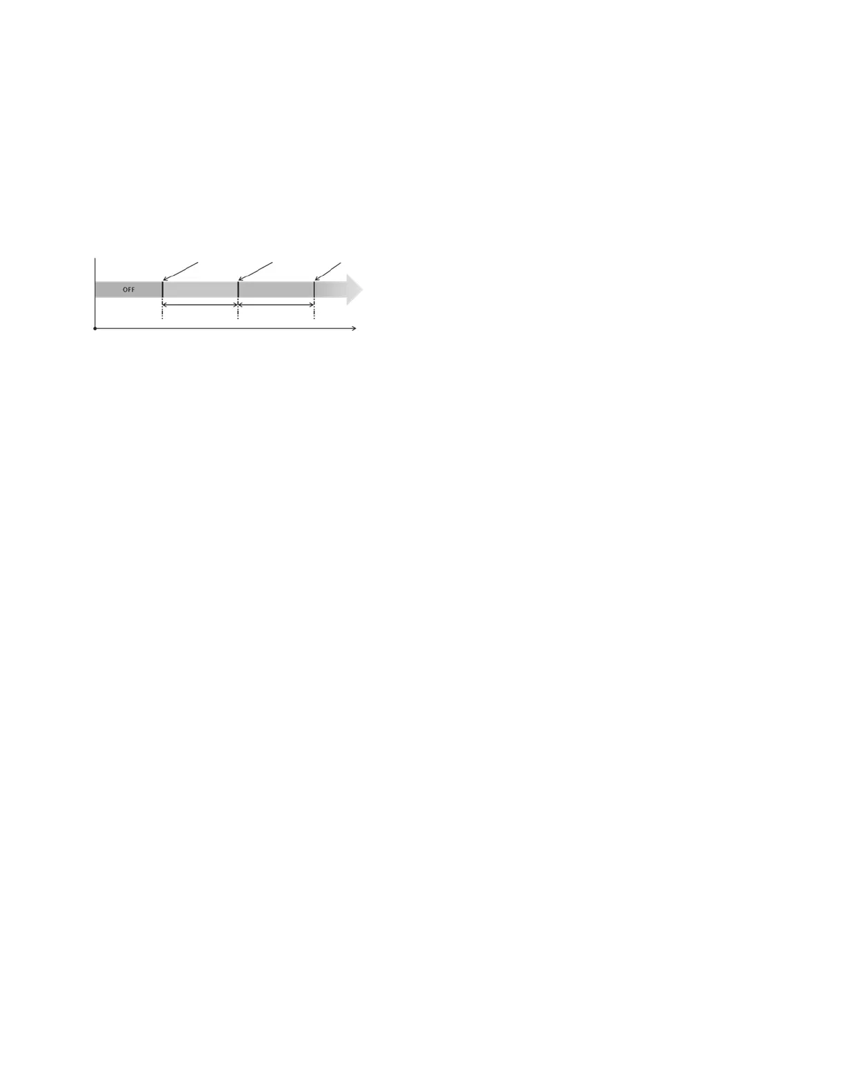
OIL RECOVERY
The oil recovery mode is enabled when the compressor speed
falls below the threshold (Trigger Speed) for a continuous peri-
od of time (Trigger Time). The mode will ramp the compressor
speed to an objective speed (Recover Speed) for a period of
time (Recover Time) and then return the compressor speed to
automatic control. This mode takes precedence over other WA-
TER_T overrides: ramp loading (Override 7), Low SP (Over-
ride 23), and Demand Limit (Override 9). See Fig. 54.
Fig. 54 — Oil Recovery Diagram
Sensors
The electronic control uses up to 15 thermistors to sense tem-
peratures and up to 10 transducers to sense pressure for con-
trolling chiller operation. These sensors are outlined below.
THERMISTORS (TABLES 36-40)
Thermistors that monitor the chiller’s operation include: evapo-
rator entering water, evaporator leaving water, dual chiller leav-
ing water, compressor suction gas temperature, compressor dis-
charge gas temperature, economizer temperature, liquid line
temperature, compressor motor temperature, and Outdoor Air
Temperature thermistors. These thermistors are 5,000 ohms at
77°F (25°C) and are identical in temperature versus resistance.
The space temperature thermistor is 10,000 ohmsat 77°F (25°C)
and has a different temperature vs. resistance. See Fig. 55 for
thermistor locations.
Evaporator Leaving Water Sensor (LWT)
On all sizes, this thermistor is installed in a threaded well in the
leaving water nozzle of the evaporator. See Fig. 56.
Evaporator Entering Water Sensor (EWT)
On all sizes, this thermistor is factory-installed in a threaded
well in the entering water nozzle of the evaporator.
Suction Gas Temperature (SGT)
On all sizes, this thermistor is factory-installed in a threaded
well located on the compressor of each circuit. There is one
thermistor for each circuit.
Compressor Discharge Gas Temperature (DGT)
On all sizes, this thermistor is factory-installed in a threaded
well located in the discharge end of the compressor for the cir-
cuit. There is one thermistor for each circuit.
Liquid Line Temperature (LIQT)
This thermistor is factory-installed in a threaded well located in
the liquid line of the circuit. There is one thermistor for each
circuit.
Economizer Temperature (ECT)
On all sizes, this thermistor is factory-installed in a threaded
well located in the economizer line for the circuit. There is one
thermistor for each circuit.
Compressor Motor Temperature (Comp Temp)
On all sizes, this thermistor is embedded in the motor wind-
ings. There are two thermistors in each compressor. One spare
is provided.
Outdoor Air Temperature (OAT)
This sensor is factory-installed to the back of the control box.
Space Temperature
This sensor (part no. 33ZCT55SPT) is a field-installed accessory
mounted in the indoor space and is used for water temperature re-
set. The sensor should be installed as a wall-mounted thermostat
would be (in the conditioned space where it will not be subjected
to either a cooling or heating source or direct exposure to sunlight,
and 4 to 5 ft above the floor).
Space temperature sensor wires are to be connected to terminals
in the unit main control box. See Fig. 57. The space temperature
sensor includes a terminal block (SEN) and a RJ11 female con-
nector. The RJ11 connector is used as access into the Carrier
Comfort Network
®
at the sensor.
To connect the space temperature sensor (see Fig. 57):
1. Using a 20 AWG twisted pair conductor cable rated for the
application, connect one wire of the twisted pair to one SEN
terminal and connect the other wire to the other SEN termi-
nal located under the cover of the space temperature sensor.
2. Connect the other ends of the wires to terminals 7 and 8 on
TB6 located in the unit control box.
Units on the CCN can be monitored from the space at the sen-
sor through the RJ11 connector, if desired. To wire the RJ11
connector into the CCN:
1. Cut the CCN wire and strip ends of the red (+), white
(ground), and black (–) conductors. (If another wire color
scheme is used, strip ends of appropriate wires.)
2. Insert and secure the red (+) wire to terminal 5 of the space
temperature sensor terminal block.
3. Insert and secure the white (ground) wire to terminal 4 of the
space temperature sensor.
4. Insert and secure the black (–) wire to terminal 2 of the space
temperature sensor.
5. Connect the other end of the communication bus cable to the
remainder of the CCN communication bus.
NOTE: The EMM is required for this accessory.
TRANSDUCERS
There are 5 pressure transducers per circuit, and two different
types of transducers: low pressure (green connector) and high
pressure (black connector).
Low Pressure Type: Suction Pressure Transducer (SPT), Econ-
omizer Pressure Transducer (EPT).
High Pressure Type: Discharge Pressure Transducer (DPT), Oil
Pressure Transducer (OPT), Liquid Pressure Transducer
(LPT). See Fig. 58 for transducer locations.
MINIMUM SPEED
TRIGGER SPEED RECOVERY SPEED
SERVICE1_odtrgspd SERVICE1_odrecspd
COMPRESSOR SPEED (Hz)
 Loading...


